
إجابة سريعة
اختيار المضخة المناسبة لضخ ملاط قاع المكثّف يتطلب مطابقة المواد مع التآكل الشديد الناتج عن التركيزات العالية من المواد الصلبة، واختيار تصميمات الدفّاعات التي تمنع الانسداد، وتهيئة المضخة للتغلب على سلوك الموائع غير النيوتونية. يصل ملاط قاع المكثّف إلى 40–70% من المواد الصلبة بالوزن ويتصرف كسائل غير نيوتوني مع إجهاد خضوع يجب التغلب عليه لبدء التدفق. عوامل الاختيار الكمية الرئيسية:
- مقاومة المواد للتآكل الشديد: دفّاعات سبيكة الكروم العالي Cr27 قد تدوم فقط 3–6 أسابيع في ملاط قاع مكثّف خام الحديد. الترقية إلى الكروم العالي Cr33 أو الفولاذ المقاوم للصدأ المزدوج تمدد عمر الخدمة إلى 6–12 شهرًا في ملاط قاع خام الحديد والنحاس. البطانات الخزفية يمكن أن تحقق 12–18 شهرًا في التطبيقات ذات الجسيمات الدقيقة والتأثير المنخفض.
- سرعة الترسيب الحرجة في خط التفريغ: يجب أن تحافظ المضخة على سرعة تدفق دنيا تبلغ 2.5–4 م/ث عبر أنبوب التفريغ بالكامل لمنع ترسب المواد الصلبة. تحت هذه السرعة، تتراكم المواد الصلبة في الأنبوب، مما يقلل القطر الفعلي ويؤدي في النهاية إلى انسدادات.
- سلوك الموائع غير النيوتونية: يُظهر ملاط قاع المكثّف إجهاد خضوع — يجب أن تولّد المضخة شفطًا كافيًا لبدء تدفق ملاط قد يقاوم الحركة عند السكون. الملاط الانسيابي الذي يتجلّط أثناء التوقف يتطلب عزم دوران مرتفع عند البدء أو قدرة تشغيل ناعم عبر محول التردد VFD.
- تصميم الدفّاعة والمدخل للملاط عالي الكثافة: الدفّاعات شبه المفتوحة أو الدوامية توفر ممر المواد الصلبة اللازم لمنع الانسداد. للملاط الذي يتجاوز 50% من المواد الصلبة، قد تكون قواديس التغذية المخروطية أو المغذيات اللولبية مطلوبة لضمان تدفق ثابت إلى شفط المضخة.
يمثل ملاط قاع المكثّف أكثر الملاط تآكلًا وصعوبة في الضخ في أي دائرة معالجة معادن. المواد الصلبة المركزة التي تستقر في قاع المكثّف — المطحونة بالفعل إلى جسيمات دقيقة في الطاحونة — تخرج الآن بكثافة قصوى، حاملة الإمكانات التآكلية الكاملة للخام. المضخة المحددة دون مراعاة التأثيرات المجتمعة لتركيز المواد الصلبة العالي، وسلوك التدفق غير النيوتوني، والحاجة إلى الحفاظ على سرعة خط الأنابيب الحرجة ستفشل بسرعة — ليس بسبب أي عيب تصنيعي، بل بسبب عدم تطابق جوهري بين تصميم المضخة والواقع الفيزيائي لملاط قاع المكثّف.
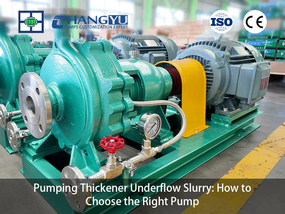
تصنع مضخات Changyu مضخات الملاط المقاومة للتآكل للتعدين ومعالجة المعادن والتطبيقات الكيميائية منذ أكثر من عقدين. يغطي هذا الدليل اختيار المواد، وميزات تصميم المضخة، والممارسات التشغيلية التي تحدد ما إذا كانت مضخة قاع المكثّف تقدم خدمة موثوقة أو تصبح مشكلة صيانة متكررة.
ما الذي يجعل ضخ ملاط قاع المكثّف صعبًا للغاية؟
A المكثّف يركز المواد الصلبة بالسماح لها بالترسيب، منتجًا ملاط قاع عالي الكثافة يقدم ثلاثة تحديات متزامنة لمعدات الضخ. فهم هذه التحديات هو أساس التحديد الصحيح للمضخة.
تركيز المواد الصلبة العالي
يحتوي ملاط قاع المكثّف عادةً على 40–70% من المواد الصلبة بالوزن — مقارنة بـ 20–35% لملاط تفريغ المطحنة التقليدي. عند هذه التركيزات، لم يعد الملاط يتصرف كسائل مع جسيمات معلقة. إنه يتصرف كـ مائع غير نيوتوني, ، مما يعني أن لزوجته تتغير مع ظروف التدفق ويظهر إجهاد خضوع — قوة دنيا يجب تطبيقها قبل أن يبدأ الملاط في الحركة على الإطلاق. يؤثر إجهاد الخضوع هذا مباشرة على أداء شفط المضخة: يجب أن يولّد الدفّاع قوة أولية كافية لسحب الملاط إلى غلاف المضخة.
سلوك التدفق غير النيوتوني والانسيابية
العديد من ملاط قاع المكثّف انسيابي — يشكل بنية شبيهة بالهلام عند السكون ويصبح أكثر سيولة عند التحريك. هذا يخلق تحديًا كبيرًا أثناء بدء تشغيل المضخة بعد فترة توقف. يجب أن تتغلب المضخة على المقاومة المتزايدة للملاط المتجلّط، مما يتطلب عزم دوران بدء أعلى. يجب أن تكون المحركات الكهربائية مخصصة لحالة البدء هذه، وليس فقط حمل التشغيل العادي. قدرة التشغيل الناعم عبر محول التردد VFD تسمح للمضخة بالتسارع تدريجيًا، مما يقلل الصدمة الميكانيكية على المحامل والوصلات والأختام.
سرعة الترسيب الحرجة
في خط أنابيب التفريغ، يجب أن تحافظ المضخة على سرعة تدفق دنيا — تُعرف بسرعة الترسيب الحرجة — لمنع ترسب المواد الصلبة إلى قاع الأنبوب. لملاط قاع المكثّف، تبلغ هذه السرعة عادةً 2.5–4 م/ث، اعتمادًا على حجم الجسيمات والكثافة والتركيز. إذا عملت المضخة بتدفق مخفض (أثناء الخفض أو أثناء ملء خط أنابيب فارغ)، تستقر المواد الصلبة في الأنبوب، مما يقلل القطر الفعلي ويزيد خسائر الاحتكاك. بمرور الوقت، يمكن للمواد الصلبة المستقرة أن تسد خط الأنابيب بالكامل — وهي مشكلة تتطلب توقفًا طويلًا لتنظيفها.
باختصار: يجب أن تتغلب المضخة على إجهاد الخضوع عند الشفط، وتحافظ على السرعة الحرجة في التفريغ، وتقاوم التآكل الناتج عن تركيز المواد الصلبة بنسبة 40–70%. هذه المتطلبات الثلاثة تحدد تحدي ضخ ملاط قاع المكثّف.
ما المواد التي تقاوم التآكل في مضخات ملاط قاع المكثّف؟
اختيار المواد هو القرار الأكثر أهمية لمضخة قاع المكثّف. مزيج التركيز العالي للمواد الصلبة، والجسيمات المعدنية الصلبة، والتشغيل المستمر يخلق بيئة تآكل أشد من أي تطبيق ضخ ملاط آخر تقريبًا.
خيارات المواد لخدمة قاع المكثّف
جدول: اختيار المواد لمضخات ملاط قاع المكثّف
| المواد | عمر الخدمة النموذجي | الأفضل لـ | القيود |
|---|---|---|---|
| خيارات المواد لخدمة تدفق العودة من التكسير | 3–6 أسابيع (خام الحديد/النحاس) | خامات منخفضة السيليكا وصلابة معتدلة؛ تطبيقات مقيدة بالميزانية | تآكل سريع في الملاط عالي السيليكا وعالي السرعة |
| 3–6 أسابيع (سرعة عالية)؛ 8–12 أسبوعًا (سرعة منخفضة) | 6–12 شهرًا | خامات عالية السيليكا (الحديد والنحاس)؛ المعيار الصناعي للخدمة الشاقة | الكروم العالي Cr33/Cr33M (700–750 HB) |
| المطاط الطبيعي | 12–18 شهرًا (جسيمات دقيقة مستديرة) | مخلفات دقيقة غير كاشطة؛ درجة حموضة محايدة | تقطيع بواسطة جسيمات حادة زاويّة؛ حد درجة حرارة 70°م |
| الفولاذ المقاوم للصدأ المزدوج 2205 | 12–24 شهرًا | ملاط قاع تآكلي (ترشيح حمضي، كلوريد عالي) | تكلفة أعلى؛ التحقق من PREN لمستويات الكلوريد |
| بطانة UHMW-PE | 12–18 شهرًا (تآكل معتدل) | التآكل والتآكل الكاشط مجتمعين؛ التدفق السفلي الكيميائي | حد درجة حرارة 90°م؛ غير مناسب للجسيمات الخشنة الحادة |
| مبطن بالسيراميك (SiC أو Al2O3) | 12–18 شهرًا (جسيمات دقيقة منخفضة التأثير)؛ 6–10 أشهر (سيليكا دقيقة عالية الصلابة) | التآكل الشديد، التدفق السفلي للجسيمات الدقيقة | هش — تأثير الجسيمات الأكبر من 2 مم قد يسبب كسرًا |
مطابقة المواد حسب نوع الخام وظروف قاع المكثّف
جدول: مطابقة المواد لتطبيقات قاع المكثّف
| نوع الخام | نطاق الأس الهيدروجيني | صلادة الجسيمات | العمر الافتراضي النموذجي (Cr27) | العمر الافتراضي النموذجي (Cr33) | الترقية الموصى بها |
|---|---|---|---|---|---|
| خام الحديد (الهيماتيت، الماجنتيت) | 6-8 | عالية (موس 5.5–6.5) | 3–6 أسابيع | 6–12 شهرًا | بطانات سيراميكية للجسيمات الدقيقة |
| خام النحاس | 4–11 (متغير) | متوسطة (موس 3.5–4) | 4–8 أسابيع | 8–14 شهرًا | دوبلكس 2205 للترشيح الحمضي |
| خام الذهب (غني بالسيليكا) | 5–9 | عالية جدًا (موس 7) | 3–6 أسابيع | 4–8 أشهر | بطانات من السيراميك أو كربيد التنجستن |
| خام الفوسفات | 2–4 (حمضي) | معتدل (موس 3–5) | 6–12 أسبوعًا | 10–16 شهرًا | مبطنة بـ UHMW-PE لمقاومة الأحماض |
| مخلفات الفحم | 5–7 | منخفض (موس 1–2) | 12–18 شهرًا | معتدل — محدود بالضغط | مطاط طبيعي للجسيمات الدقيقة |
لاحظ مهندسو مضخات Changyu عبر مئات تركيبات مضخات تدفق قاع المثخن: في تدفق قاع خام الحديد وخام الذهب الغني بالسيليكا، فإن الكروم العالي Cr27 ليس مادة كافية للخدمة المستمرة — فالتآكل في الدفاعة والحلزون خلال 3–6 أسابيع أمر شائع. يوفر الترقية إلى الكروم العالي Cr33 أو Cr33M تحسنًا كبيرًا، بينما توفر بطانات السيراميك أو كربيد التنجستن أطول عمر خدمة عندما يكون حجم الجسيمات ضمن حدود مقاومة الصدمات للمادة. يُظهر تحليل التكلفة الإجمالية للملكية أنه بينما تحمل المواد عالية الجودة تكلفة أولية أعلى، فإنها تُسترد من خلال إلغاء عمليات استبدال المضخات وتقليل وقت توقف المثخن.
لماذا يعتبر تصميم المضخة مهمًا لضخ تدفق قاع المثخن؟
يجب أن يعالج تصميم مضخة تدفق قاع المثخن ثلاثة متطلبات متزامنة: التغلب على إجهاد الخضوع عند الشفط، ومنع الانسداد في الدفاعة، والحفاظ على السرعة الحرجة في التفريغ. قد لا تلبي تصاميم مضخات الملاط القياسية جميع المتطلبات الثلاثة في خدمة تدفق القاع عالي التركيز.
تصميم الشفط: التغلب على إجهاد الخضوع والسلوك الانسيابي
عندما يكون تدفق قاع المثخن ثابتًا — بعد إيقاف التشغيل أو أثناء التشغيل المتقطع — قد يطور الملاط بنية هلامية تقاوم الحركة الأولية. يجب تصميم شفط المضخة لسحب هذه المادة إلى الهيكل:
- قطر شفط كبير: فوهة شفط لا يقل قطرها عن 1.5× قطر مدخل المضخة (حتى 2× لتدفق القاع الذي يتجاوز 60% مواد صلبة) تقلل من خسائر الدخول وتسمح للمواد الصلبة المستقرة بدخول المضخة.
- قادوس تغذية مخروطي: لتدفق القاع الذي يتجاوز 50% مواد صلبة، يقوم قادوس مخروطي بزوايا جدار حادة (عادة 60–70° من الأفقي) بتوجيه الملاط إلى شفط المضخة بالجاذبية، مما يقلل حمل الشفط على المضخة.
- مغذي لولبي: لأعلى التركيزات (> 60% مواد صلبة) أو الملاط الانسيابي الذي يتجمد بشدة أثناء إيقاف التشغيل، يدفع مغذي لولبي مثبت فوق شفط المضخة الملاط بنشاط إلى الدفاعة، مما يضمن تغذية إيجابية بغض النظر عن إجهاد الخضوع.
اختيار الدفاعة للملاط عالي الكثافة
جدول: اختيار الدفاعة لمضخات تدفق قاع المثخن
| نوع المكره | ممر المواد الصلبة | الكفاءة | الأفضل لـ |
|---|---|---|---|
| شبه مفتوح | معتدل (حتى 50 مم) | 50–60% | تدفق قاع مثخن قياسي مع مواد صلبة معتدلة |
| دوامية (غائرة) | كبير (حتى 100 مم) | 35–55% | مواد صلبة عالية، حجم جسيمات غير متوقع؛ أقصى مقاومة للانسداد |
| قناة (مفردة/مزدوجة) | معتدل | 55-70% | تدفق قاع بتركيز أقل؛ كفاءة أعلى |
يوصي مهندسو تشانغيو بومب بما يلي: لتدفق قاع المثخن الذي يتجاوز 50% تركيز المواد الصلبة، توفر الدفاعة الدوامية أو الدفاعة شبه المفتوحة مع قادوس تغذية مخروطي المزيج الأكثر موثوقية من مرور المواد الصلبة وأداء الشفط. عقوبة الكفاءة للدفاعة الدوامية غير ذات أهمية اقتصادية مقارنة بتكلفة تنظيف مضخة مسدودة في خدمة تدفق قاع المثخن — خاصة عندما يجب إيقاف تشغيل المثخن للوصول إلى المضخة.
اعتبارات بدء التشغيل للملاط الانسيابي
يتطلب ملاط تدفق القاع الانسيابي الذي يتجمد أثناء إيقاف التشغيل إدارة دقيقة لبدء التشغيل. يقلل بدء التشغيل الناعم عبر VFD من الصدمة الميكانيكية للتغلب على إجهاد الخضوع للملاط المتجمد. للمضخات بدون قدرة VFD، يوفر اختيار مضخة بمنحنى رأس حاد تدفقًا أكثر اتساقًا مع انتقال الملاط من الحالة الهلامية إلى الحالة السائلة.
أين تُستخدم مضخات تدفق قاع المثخن؟
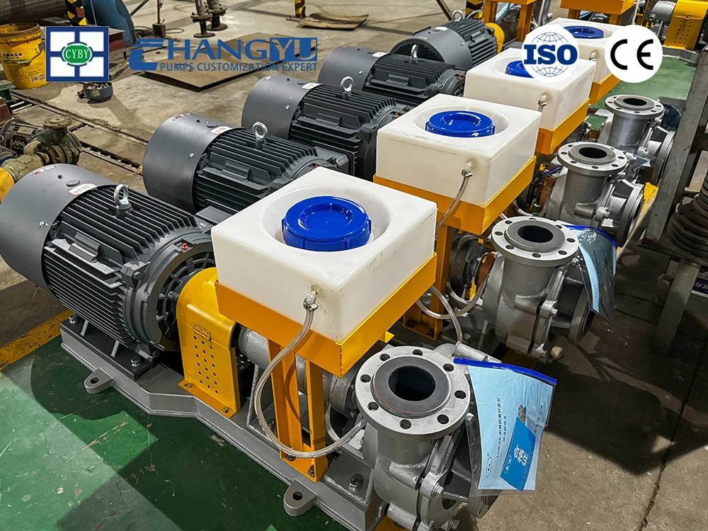
تعمل مضخات تدفق قاع المثخن في الصناعات التي ينتج فيها فصل المواد الصلبة والسائلة تيار تدفق قاع عالي الكثافة يجب نقله لمزيد من المعالجة أو التخلص.
معالجة المعادن
التطبيق الأكثر شيوعًا. في مراكز تركيز خام الحديد والنحاس والذهب والفوسفات، تنقل مضخات تدفق قاع المثخن ملاط الخام المركز إلى الترشيح أو التخلص من المخلفات أو مرحلة المعالجة التالية. تتراوح معدلات التدفق من عشرات إلى مئات الأمتار المكعبة في الساعة، مع تركيزات مواد صلبة من 40% إلى أكثر من 65%. التآكل هو آلية التآكل السائدة، حيث تحدد صلابة الخام مواصفات المواد المطلوبة.
إزالة الكبريت من غاز المداخن (FGD)
في أنظمة إزالة الكبريت من غاز المداخن الرطبة (FGD) بالحجر الجيري، يتم تكثيف تيار نزيف الممتص لاستعادة الجبس. تنقل مضخة تدفق قاع المثخن ملاط الجبس بتركيز 40–55% مواد صلبة إلى الترشيح أو نزح المياه. يحتوي الملاط على كبريتات الكالسيوم (الجبس) مع حجر جيري متبقٍ، ويمكن أن تصل تركيزات الكلوريد إلى 30,000 ملجم/لتر. يتطلب الجمع بين التآكل المعتدل وتآكل الكلوريد العالي مكونات مبللة من الفولاذ المقاوم للصدأ المزدوج.
الترسيب الكيميائي والتكثيف الصناعي
في إنتاج حمض الفوسفوريك وتكرير الألومينا ومعالجة مياه الصرف الصناعي، تنتج مثخنات الترسيب الكيميائي تدفق قاع يحتوي على رواسب كيميائية دقيقة. غالبًا ما تكون هذه الملاط حمضية (pH 1–4) وقد تحتوي على جسيمات بلورية حادة. يجب أن يعالج اختيار المواد كلاً من التآكل والتآكل السطحي — المضخات المبطنة بـ UHMW-PE أو الفولاذ المقاوم للصدأ المزدوج هي المواصفات القياسية.
كيفية التعامل مع الضخ لمسافات طويلة لتدفق قاع المثخن؟
عندما يجب نقل تدفق قاع المثخن لمسافات طويلة — مثل نقلها إلى منشأة تخزين مخلفات بعيدة — يجب أن تولد المضخة ضغطًا كافيًا للتغلب على خسائر احتكاك الأنابيب مع الحفاظ على سرعة الترسيب الحرجة طوال خط الأنابيب.
تكوين المضخة متعددة المراحل
للنقل لمسافات طويلة الذي يتطلب رؤوسًا أعلى مما يمكن أن توفره مضخة واحدة، يتم ترتيب مضخات متعددة على التوالي. تضيف كل مضخة رأسها إلى الضغط الكلي للنظام. عند ترتيب المضخات على التوالي:
- استخدم نماذج مضخات متطابقة: المضخات غير المتطابقة ذات منحنيات الأداء المختلفة تسبب توزيعًا غير متساوٍ للحمل — قد تعمل إحدى المضخات عند الإغلاق بينما تعمل أخرى عند أقصى تدفق، مما يسرع التآكل في كلتيهما.
- قم بتركيب صمامات فحص: يمنع صمام الفحص في اتجاه مجرى كل مضخة التدفق العكسي إذا تعطلت إحدى المضخات، مما يحمي المضخات العلوية من الدوران العكسي و المطرقة المائية.
- طابق سرعة خط الأنابيب: يجب أن يحافظ معدل التدفق عبر جميع المضخات المتسلسلة على سرعة الترسيب الحرجة في كل قسم من خط أنابيب التفريغ. يوفر مقياس التدفق مع إنذار التدفق المنخفض تحذيرًا مبكرًا إذا انخفضت سرعة خط الأنابيب عن الحد الآمن.
الحماية من النبض والارتفاع المفاجئ
يمكن للمضخات الطاردة المركزية التي تعمل على التوالي أن تولد تقلبات في الضغط تشكل إجهادًا على دعامات الأنابيب وأجهزة القياس وأختام الصمامات. قم بتركيب دعامات أنابيب كافية ووصلات تمدد للتحكم في هذه التقلبات. بالنسبة لخطوط الأنابيب ذات التغيرات الكبيرة في الارتفاع، يوفر خزان التخفيف عند النقطة العليا حماية من المطرقة المائية الناتجة عن توقف المضخات أو إغلاق الصمامات.
كيف تختار المضخة المناسبة لملاط قاع المكثف؟
يتطلب اختيار مضخة ملاط قاع المكثف مطابقة المواد وتصميم المروحة وتكوين الشفط مع الخصائص المحددة للملاط في كل موقع تركيب.
مشكلات وحلول شائعة في ضخ ملاط قاع المكثف
جدول: مشكلات وحلول شائعة في ضخ ملاط قاع المكثف
| المشكلة | السبب الجذري | الحل |
|---|---|---|
| تآكل المروحة خلال أسابيع | Cr27 عالي الكروم غير كافٍ لصلابة الخام | الترقية إلى Cr33 أو دوبلكس 2205 أو بطانات سيراميكية |
| تفشل المضخة في سحب الملاط بعد التوقف | الملاط الانسيابي تحول إلى هلام؛ إجهاد الخضوع مرتفع جدًا | تركيب بداية ناعمة VFD؛ إضافة قادوس تغذية مخروطي أو وحدة تغذية لولبية |
| انسداد خط الأنابيب | سرعة التدفق أقل من سرعة الترسيب الحرجة | زيادة سرعة المضخة؛ تقليل قطر الأنبوب لرفع السرعة |
| فشل الختم خلال أسابيع | دخول المواد الصلبة إلى حجرة الختم؛ لا يوجد نظام غسيل | تركيب شطف API Plan 32 أو ختم طرد مركزي |
| ضوضاء التجويف والاهتزاز | NPSHa غير كافٍ للملاط عالي الكثافة | خفض ارتفاع المضخة؛ زيادة قطر أنبوب الشفط |
| تحميل زائد للمحرك عند بدء التشغيل | ملاط متجمد يتطلب عزم دوران مرتفع للبدء | تركيب VFD مع زمن تسارع ممتد؛ تكبير حجم المحرك لظروف البدء |
عملية اختيار مضخة ملاط قاع المكثف من ست خطوات
الخطوة 1: توصيف ملاط قاع المكثف.
تحديد تركيز المواد الصلبة (% بالوزن)، وتوزيع حجم الجسيمات، وصلابة الخام (مقياس موس)، وشكل الجسيمات، ودرجة الحموضة pH، وتركيز الكلوريد، ودرجة الحرارة.
الخطوة 2: تحديد المتطلبات الهيدروليكية.
حساب معدل التدفق المطلوب، وإجمالي الرأس الديناميكي (بما في ذلك الرفع الثابت وفقدان احتكاك الأنابيب)، والتحقق من أن سرعة التدفق عبر خط التفريغ تتجاوز سرعة الترسيب الحرجة (2.5–4 م/ث).
الخطوة 3: اختيار المواد.
مطابقة المواد الملامسة للسائل مع صلابة الخام ودرجة الحموضة وخصائص الجسيمات وفقًا للمصفوفة في القسم 2. بالنسبة لخام الحديد والملاط الغني بالسيليكا، فإن Cr33 عالي الكروم هو الحد الأدنى المقبول من الدرجات.
الخطوة 4: اختيار نوع المروحة وتكوين الشفط.
مطابقة تصميم المروحة مع تركيز المواد الصلبة وخطر الانسداد. لملاط قاع المكثف الذي يزيد تركيزه عن 50% من المواد الصلبة، حدد مروحة دوامية أو شبه مفتوحة مع قادوس تغذية مخروطي أو وحدة تغذية لولبية.
الخطوة 5: تحديد ترتيب الختم.
للملاط الكاشط، قم بتركيب غسيل خارجي API Plan 32 لحماية أسطح الأختام. للمواقع النائية بدون مياه غسيل، حدد أختام طرد طاردة مركزية مع حشوة غدة.
الخطوة 6: التحقق من ظروف البدء.
للملاط الانسيابي، تحقق من أن عزم دوران المحرك يتجاوز إجهاد الخضوع للملاط المتجمد. قم بتركيب بداية ناعمة VFD واضبط زمن التسارع لتقليل الصدمة الميكانيكية.
يوصي مهندسو تشانغيو بومب بما يلي: عندما يتعامل المكثف مع أنواع متغيرة من الخامات، اختر مواد المضخة لأكثر الخامات كشطًا في خطة المنجم — وليس المتوسط. المضخة المحددة للظروف المتوسطة ستشهد تآكلًا متسارعًا كلما تمت معالجة خام أكثر صلابة، مما يؤدي إلى توقف غير مخطط له. التكلفة الإضافية للترقية من Cr27 إلى Cr33 تُسترد عدة مرات من خلال تجنب استبدال المضخات.
دراسة حالة لضخ ملاط قاع المكثف: حل مشكلة العمر القصير لمضخة ملاط قاع المكثف
قام مصنع تركيز خام الحديد في أستراليا بتشغيل ثلاث مضخات طاردة مركزية على ملاط قاع مكثف المخلفات. المواصفات الأصلية: مكونات مبللة من Cr27 عالي الكروم مع أختام ميكانيكية مفردة. ظروف ملاط قاع المكثف: 55–60% مواد صلبة بالوزن، خام مغنيتيت غني بالسيليكا (موس 6–6.5)، حجم الجسيمات 100–500 ميكرومتر، تشغيل متقطع مع توقفات يومية.
تطلبت المضخات استبدال المروحة كل 3–4 أسابيع. أظهرت بطانات الحلزون أخاديد عميقة عند نقطة القطع بعد 6–8 أسابيع. فشلت الأختام الميكانيكية كل 4–6 أسابيع بسبب دخول المواد الصلبة. كل استبدال مضخة تطلب 3–4 ساعات من التوقف، وخلالها تم تحويل ملاط قاع المكثف إلى بركة طوارئ — مما تطلب عمليات استرداد مكلفة.
حدد تحليل السبب الجذري أن Cr27 عالي الكروم (650–700 HB) كان يُقطع بواسطة جزيئات السيليكا (800–1,000 HV) عند تركيز المواد الصلبة المرتفع. الطبيعة الانسيابية لملاط قاع المكثف — الذي يتجمد خلال التوقفات اليومية — كانت تسبب عزم دوران بدء مفرطًا أدى إلى تسريع تآكل المحامل والوصلات. الأختام الميكانيكية المفردة كانت تفتقر إلى أنظمة الغسيل، مما سمح لجزيئات الخام الدقيقة بدخول حجرة الختم.
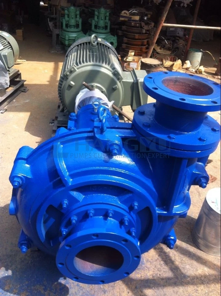
استبدل المصنع جميع المضخات الثلاث بمضخات Changyu PGY Series بمكونات مبللة من Cr33M عالي الكروم، وواجهة مروحة من كربيد التنجستن، وأختام طرد طاردة مركزية مع حشوة غدة. تم تركيب بداية ناعمة VFD للتحكم في إجهاد الخضوع للملاط المتجمد أثناء البدء. التصميم مزدوج الغلاف سمح باستبدال سريع للأجزاء المبللة دون فصل أنابيب الشفط والتفريغ.
على مدى 12 شهرًا من التشغيل: امتد عمر المروحة من 3–4 أسابيع إلى أكثر من 6 أشهر. تم القضاء على فشل الأختام الميكانيكية. انخفض وقت توقف استبدال المضخات بأكثر من 80%. تم استرداد تكلفة استبدال المضخات خلال 4 أشهر من خلال القضاء على الصيانة الطارئة وتقليل توقف المكثف.
النقطة الرئيسيةالخلاصة: في خدمة ملاط قاع المكثف، فإن Cr27 عالي الكروم ليس مادة كافية للخامات الغنية بالسيليكا. يوفر Cr33 عالي الكروم مع واجهة كربيد التنجستن مقاومة التآكل اللازمة للتشغيل الموثوق. أختام الطرد الطاردة المركزية تلغي الاعتماد على مياه الغسيل الذي يجعل الأختام الميكانيكية غير موثوقة في ملاط قاع المكثف الكاشط. بداية ناعمة VFD ضرورية للملاط الانسيابي الذي يتجمد أثناء التوقف.
حلول مضخات ملاط قاع المكثف من Changyu Pump
تقدم Changyu Pump ثلاث سلاسل مضخات مناسبة لتطبيقات ملاط قاع المكثف عبر صناعات التعدين ومعالجة المعادن والصناعات الكيميائية. كل سلسلة تعالج مجموعات محددة من شدة الكشط وإمكانات التآكل ومتطلبات التدفق.
دليل اختيار منتج مضخة ملاط قاع المكثف
جدول: دليل اختيار منتج مضخة ملاط قاع المكثف
| التطبيق | التحدي الرئيسي | السلسلة الموصى بها | الميزة الرئيسية |
|---|---|---|---|
| ملاط قاع مكثف كبير (تدفق مرتفع، رأس مرتفع) | تدفق مرتفع + نقل لمسافات طويلة | سلسلة PGY | تدفق 117–976 م³/ساعة؛ رفع حتى 101.6 م؛ كروم عالي Cr33M |
| ملاط كيميائي/تآكلي | تآكل + تآكل معتدل | سلسلة UHB | تدفق 3–2,600 م³/ساعة؛ مبطن بـ UHMW-PE لمقاومة مركبة |
| الملاط المسبب للتآكل (تدفق أصغر) | حمض/كلوريد + كشط | سلسلة HB | التدفق 10–60 م³/ساعة؛ ثنائي 2205/2507 لمقاومة التآكل |
ملاحظة: يتوفر Cr27 للتطبيقات منخفضة الكشط فقط. بالنسبة لتدفق قاع المثخن، يُوصى باستخدام Cr33 أو أعلى.
سلسلة PGY — مضخة الطين عالية الرفع للخدمة الشاقة لتدفق قاع المثخن
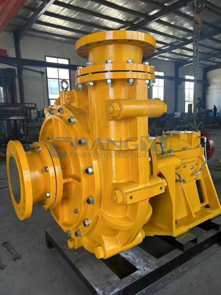
مصممة لظروف الرفع العالي والتآكل الشديد. يسمح البناء مزدوج الغلاف باستبدال الأجزاء الملامسة للسائل دون تفكيك الأنابيب — وهي ميزة حاسمة عندما يجب تقليل وقت توقف المثخن إلى الحد الأدنى. تضمن مجموعة المحامل المزيتة بالزيت موثوقية طويلة الأمد تحت التشغيل المستمر عالي الحمل. يتيح التصميم عالي الرفع (حتى 101.6 م) النقل المباشر من المثخن إلى تخزين المخلفات دون مضخات معززة وسيطة.
| المعلمة | المواصفات |
|---|---|
| معدل التدفق | 117–976 متر مكعب/ساعة |
| الرأس | 1–101.6 متر |
| قوة المحرك | 22–560 كيلوواط |
| السرعة | 730 / 980 / 1,480 دورة/دقيقة |
| المواد | BTMCr27 / BTMCr28 / BTMCr33 / فولاذ مقاوم للصدأ مزدوج |
سلسلة UHB — مضخة مبطنة بـ UHMW-PE للمياه السفلية المسببة للتآكل والكشط
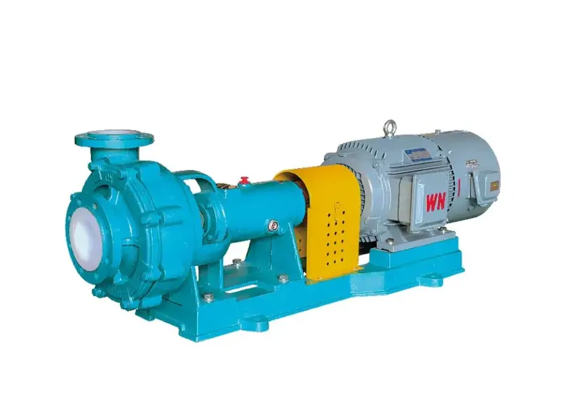
مضخة طرد مركزي مبطنة بالفولاذ بـ UHMW-PE لمياه التخثير السفلية التي تحتوي على إضافات كيميائية أو مياه عمليات حمضية. توفر مادة UHMW-PE مقاومة تآكل مجمعة ومقاومة كشط فائقة بتكلفة أقل من المضخات المعدنية بالكامل. تتعامل المروحة شبه المفتوحة مع تراكيز صلبة معتدلة. يغطي نطاق التدفق الواسع من 3 إلى 2,600 م³/ساعة تطبيقات من المصانع التجريبية إلى المكثفات الكبيرة.
| المعلمة | المواصفات |
|---|---|
| معدل التدفق | 3-2,600 متر مكعب/ساعة |
| الرأس | 5-100 m |
| قوة المحرك | 0.75-300 كيلوواط |
| السرعة | 750-2,900 دورة/دقيقة |
| درجة الحرارة | -20 درجة مئوية إلى 90 درجة مئوية |
| مادة التبطين | UHMW-PE |
سلسلة HB — مضخة من الفولاذ المقاوم للصدأ لتطبيقات المياه السفلية المسببة للتآكل
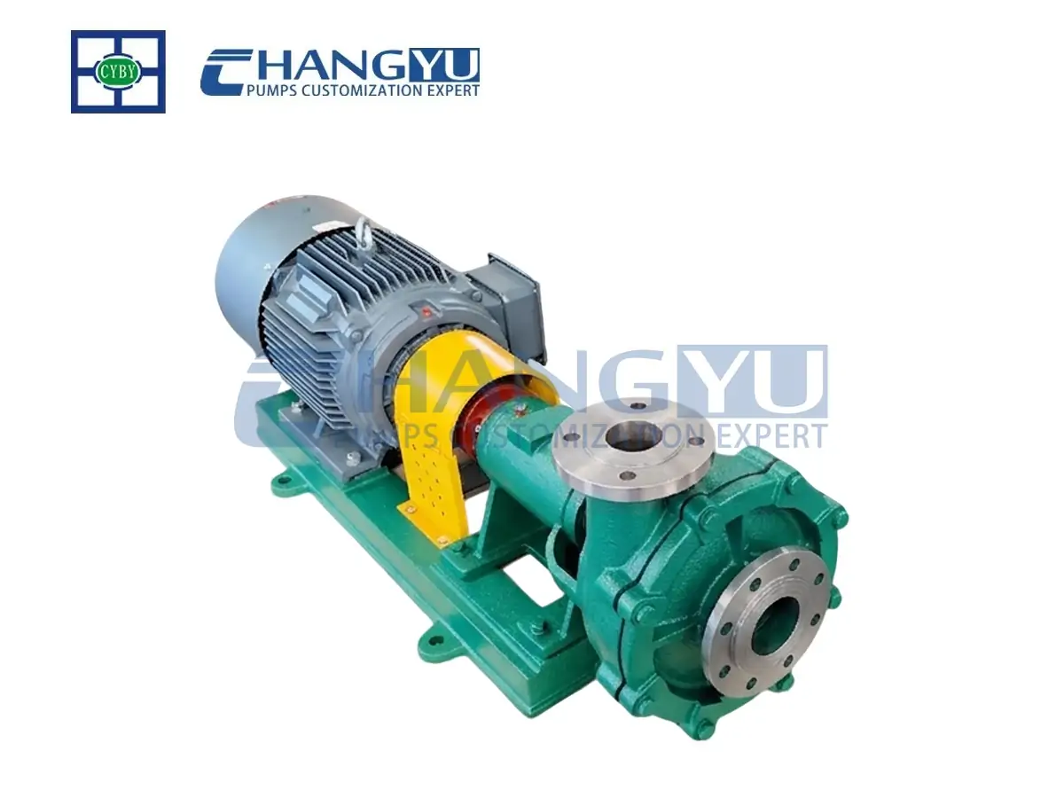
مضخة طرد مركزي أفقية متوافقة مع ISO 2858 ببنية مبللة من الفولاذ المقاوم للصدأ بالكامل. متوفرة في 316L و duplex 2205 و super duplex 2507. مناسبة لمياه التخثير السفلية في دوائر الترشيح الحمضية، وتكثيف الجبس في أنظمة إزالة الكبريت من الغاز، وعمليات الترسيب الكيميائي حيث يكون التآكل هو التحدي الأساسي. نطاق التدفق 10–60 م³/ساعة يناسب تطبيقات المكثفات الصغيرة والمصانع التجريبية.
| المعلمة | المواصفات |
|---|---|
| معدل التدفق | 10-60 م³/ساعة |
| الرأس | 20-120 m |
| قوة المحرك | 3-45 كيلوواط |
| السرعة | 2,900 دورة/دقيقة |
| درجة الحرارة | -20 درجة مئوية إلى 120 درجة مئوية |
| المواد | 304 / 316L / 2205 / 2507 |
الأسئلة الشائعة حول ضخ ملاط المياه السفلية من المكثفات
س: ما الذي يجعل المياه السفلية من المكثفات صعبة الضخ إلى هذا الحد؟
ج: تجمع المياه السفلية من المكثفات ثلاثة تحديات: تركيز صلب مرتفع للغاية (40–70% بالوزن)، وسلوك مائع غير نيوتوني مع إجهاد خضوع يقاوم التدفق الأولي، والحاجة إلى الحفاظ على سرعة الترسيب الحرجة (2.5–4 م/ث) عبر خط التفريغ بالكامل لمنع ترسب المواد الصلبة.
س: ما المادة التي تدوم أطول في خدمة مضخات المياه السفلية من المكثفات؟
ج: الكروم العالي Cr33/Cr33M (700–750 HB) يوفر عمرًا للجزء المبلل من 6 إلى 12 شهرًا في المياه السفلية الغنية بخام الحديد والسيليكا. تعمل البطانات الخزفية على تمديد عمر الخدمة إلى 12–18 شهرًا للمياه السفلية ذات الجسيمات الدقيقة ومنخفضة الصدمات. يتم تحديد duplex 2205 للمياه السفلية المسببة للتآكل حيث تكون مقاومة الكلوريدات أو الأحماض مطلوبة.
س: لماذا تفشل مضخة المياه السفلية من المكثفات في سحب الملاط بعد التوقف؟
ج: تشكل الملاطات السفلية الانسيابية بنية هلامية عند السكون. يجب أن تتغلب المضخة على إجهاد خضوع هذا الهلام لبدء التدفق. قم بتركيب بدء ناعم VFD، أو استخدم قادوس تغذية مخروطي بزوايا جدار حادة، أو أضف مغذيًا لولبيًا للمياه السفلية التي تتجاوز 60% من المواد الصلبة.
س: كيف أمنع انسداد خطوط الأنابيب في خدمة المياه السفلية من المكثفات؟
ج: حافظ على سرعة التدفق أعلى من سرعة الترسيب الحرجة — عادة 2.5–4 م/ث اعتمادًا على حجم الجسيمات والتركيز. قم بتركيب مقياس تدفق مع إنذار انخفاض التدفق. للتشغيل المتقطع، اشطف خط الأنابيب بالماء قبل فترات التوقف الطويلة.
س: هل يمكنني استخدام نفس المضخة للمياه السفلية من المكثفات وتفريغ المطحنة؟
ج: غير موصى به. تحتوي المياه السفلية من المكثفات على تركيز صلب أعلى وتتطلب تصميم شفط مختلفًا (مدخل أكبر، وربما قادوس تغذية). يحتوي تفريغ المطحنة على جسيمات خشنة ومعدلات تدفق أعلى. مواصفات مضخة منفصلة لكل مهمة تعزز الموثوقية.
س: ما ترتيب الختم الأفضل لمضخات المياه السفلية من المكثفات؟
ج: للمواقع التي تتوفر فيها مياه شطف نظيفة، يوفر الشطف الخارجي API Plan 32 حماية موثوقة لسطح الختم. للمواقع النائية دون مياه شطف، تلغي أختام الطرد المركزي مع حشو الغدة الاعتماد على المياه الخارجية تمامًا.
قائمة مراجعة إجراءات الوقاية لمهندسي مضخات تشانغيو
- لا تحدد الكروم العالي Cr27 للمياه السفلية الغنية بالسيليكا (خام الحديد، خام الذهب). معدل التآكل غير مقبول. الكروم العالي Cr33 هو الحد الأدنى الموصى به.
- احسب سرعة الترسيب الحرجة للمياه السفلية الخاصة بك — وليس فقط فقدان الاحتكاك في الأنبوب. قد يكون خط الأنابيب المصمم لفقدان الاحتكاك وحده أكبر من اللازم لتعليق المواد الصلبة، مما يسمح بالترسب عند معدلات التدفق التشغيلية العادية.
- للمياه السفلية الانسيابية التي تتجمد أثناء التوقف، قم بتركيب بدء ناعم VFD وتحقق من أن عزم بدء التشغيل للمحرك يتجاوز إجهاد خضوع الملاط المتجمد.
- للمياه السفلية التي تتجاوز 50% من المواد الصلبة، فكر في قادوس تغذية مخروطي بزوايا جدار حادة (60–70°) لضمان تدفق ثابت إلى شفط المضخة.
- حافظ على سرعة خط تفريغ أعلى من 2.5–4 م/ث. قم بتركيب مقياس تدفق مع إنذار انخفاض التدفق لتوفير تحذير مبكر إذا انخفضت السرعة عن الحد الحرج.
- للمواقع النائية دون مياه شطف نظيفة، حدد أختام الطرد المركزي مع حشو الغدة. لا تعتمد على شاحنات المياه لشطف الختم — فتفويت تسليم واحد يسبب فشلًا كارثيًا للختم.
- عند ترتيب المضخات على التوالي للنقل لمسافات طويلة، استخدم نماذج مضخات متطابقة مع منحنيات أداء متطابقة. تسبب المضخات غير المتطابقة توزيعًا غير متساوٍ للحمل وتآكلًا مبكرًا.
- احتفظ بمجموعة جزء مبلل احتياطية في المخزون لمضخات المياه السفلية الحرجة من المكثفات. تكلفة المضخة الاحتياطية تافهة مقارنة بتكلفة توقف المكثف.
الخاتمة
اختيار مضخة لملاط المياه السفلية من المكثفات يختلف جوهريًا عن تحديد مضخة لأي خدمة ملاط أخرى. إن الجمع بين تركيز صلب 40–70%، وسلوك تدفق غير نيوتوني، والحاجة إلى الحفاظ على سرعة خط الأنابيب الحرجة يخلق تحدي ضخ لا يمكن لمضخات الملاط القياسية معالجته بشكل موثوق. ثلاثة قرارات تحدد موثوقية المضخة: اختيار المادة المطابق لصلابة الخام وكيميائيته، وتصميم المضخة الذي يتغلب على إجهاد الخضوع والسلوك الانسيابي، وتكوين النظام الذي يحافظ على سرعة الترسيب الحرجة عبر خط التفريغ بالكامل.
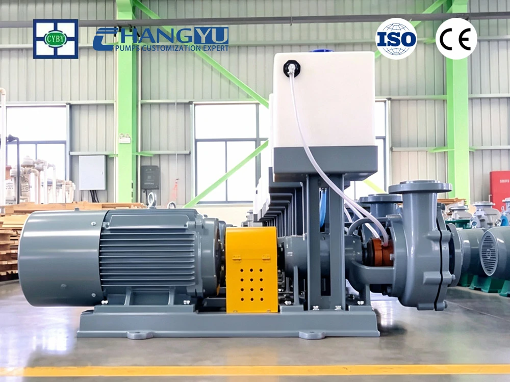
عندما تكون مستعدًا لتحديد مضخة مياه سفلية من المكثفات لتطبيقك، يمكن لفريق الهندسة في Changyu Pump توفير تقييم فني يغطي توصيف الملاط، وتوصية المواد، وتكوين المضخة المطابق لمعايير التشغيل الخاصة بك. عقدان من تصنيع المضخات المقاومة للتآكل عبر التعدين ومعالجة المعادن والتطبيقات الكيميائية يدعم كل توصية.