
1. Introduction
Pompe centrifuge en ligne Le choix d'une pompe est avant tout une question d'espace, d'intégration des canalisations et de compromis en matière de maintenance. Contrairement aux pompes à aspiration axiale qui reposent sur des fondations en béton et dont les canalisations d'aspiration et de refoulement sont séparées, une pompe en ligne est conçue pour être montée directement dans la canalisation : ses brides d'aspiration et de refoulement sont alignées sur un même axe. Cette caractéristique de conception unique élimine le besoin d'une plaque de base, simplifie le tracé de la tuyauterie en supprimant les coudes et les déviations nécessaires pour acheminer le flux à travers un corps de pompe en L, et permet un gain d'espace considérable : les pompes à aspiration en bout nécessitent généralement 20 à 60 % plus d'espace au sol que les pompes en ligne de capacité similaire.
Ce guide constitue un ouvrage de référence structuré qui couvre les connaissances essentielles dont les ingénieurs ont besoin pour définir pompes centrifuges en ligne de manière efficace — depuis les principes de fonctionnement et la comparaison critique avec les pompes à aspiration axiale jusqu'à la classification des types de pompes, en passant par un cadre de sélection étape par étape et les meilleures pratiques d'installation. Forts de plus de vingt ans d'expérience dans la conception de solutions de pompes centrifuges et résistantes à la corrosion, Pompe Changyu apporte une expertise reconnue dans les domaines des pompes à flux vertical, des pompes à pipeline et des pompes à revêtement en fluoroplastique. Contactez nous en indiquant les paramètres de votre système pour obtenir une recommandation personnalisée.
2. Qu'est-ce qu'une pompe centrifuge en ligne ?
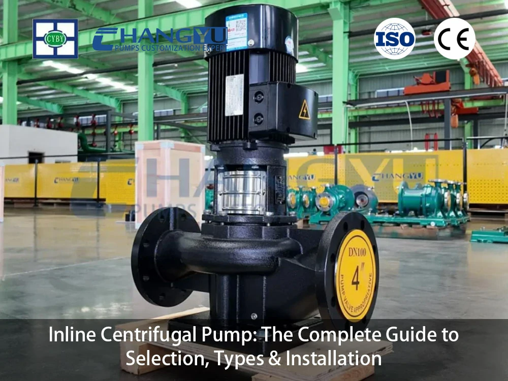
Un pompe centrifuge en ligne Il s'agit d'une pompe rotodynamique dont les raccords d'aspiration et de refoulement sont alignés sur un même axe, ce qui permet de l'installer directement dans un tronçon de tuyauterie droit sans fondation ni socle distinct — pour les petites pompes, généralement d'une puissance inférieure à 15 CV. Les pompes en ligne plus grandes (15 HP et plus) peuvent nécessiter un montage au sol ou des supports structurels supplémentaires en raison de leur poids et des charges dynamiques qu'elles génèrent. Le terme “ en ligne ” décrit la géométrie du trajet d'écoulement — le fluide entre et sort de la pompe le long de la même ligne centrale — plutôt qu'une conception spécifique de la roue ou une architecture de pompe particulière. La différence entre une pompe en ligne et une pompe standard réside dans le fait que les raccords d'aspiration et de refoulement d'une pompe en ligne sont alignés sur un seul axe.
2.1 Le circuit d'écoulement en ligne : en quoi diffère-t-il de l'aspiration en bout ?
Dans une pompe centrifuge à aspiration en bout classique, le fluide pénètre horizontalement par la bride d'aspiration, traverse la roue et ressort verticalement à un angle de 90 degrés par rapport à l'entrée — un parcours en forme de L qui nécessite des coudes, des déviations et des supports de tuyauterie supplémentaires pour intégrer la pompe au réseau de tuyauterie. Dans une pompe en ligne, l'aspiration et le refoulement se trouvent sur le même axe. Le fluide entre axialement, passe à travers la roue et sort axialement le long du même axe. Ce trajet d'écoulement en ligne droite minimise les changements de direction, réduisant ainsi la turbulence et les pertes d'énergie associées, tout en permettant à la pompe de fonctionner comme un segment de la tuyauterie elle-même.
2.2 Éléments clés
Les principaux composants d'une pompe centrifuge en ligne reflètent sa conception compacte et intégrée :
- Boîtier : Il abrite les composants internes et guide le flux de fluide. Le corps de pompe intègre les brides d'aspiration et de refoulement sur un même axe.
- Roue : L'élément rotatif qui transforme l'énergie mécanique du moteur en énergie cinétique dans le fluide. La plupart des pompes en ligne utilisent des roues radiales ou semi-axiales. La plupart des pompes centrifuges en ligne étant équipées d'une roue radiale, l'axe de rotation de la roue est perpendiculaire à l'axe commun des raccords, de sorte que le flux est dévié d'environ 90° avant d'entrer dans la roue. Ce changement de direction du flux à l'entrée génère une poussée axiale supplémentaire qui doit être absorbée par le palier de butée de la pompe ou les paliers du moteur, une considération de conception qui influe sur la durée de vie des paliers dans les applications en service continu.
- Arbre : Relie la roue au moteur, transmettant ainsi l'énergie de rotation. Souvent fabriqué en acier inoxydable.
- Roulements : Ils soutiennent l'arbre et réduisent les frottements pendant le fonctionnement. Dans les pompes verticales en ligne, les paliers du moteur soutiennent souvent également l'arbre de la pompe dans les modèles à couplage direct.
- Garniture mécanique ou garniture d'étanchéité : Empêche les fuites de liquide le long de l'arbre, à l'endroit où celui-ci sort du corps de pompe.
- Moteur : Alimente la pompe. Les pompes en ligne utilisent généralement des moteurs standard à refroidissement par air et à bride. Dans les modèles à couplage direct, la roue est montée directement sur l'arbre du moteur ; dans les modèles à couplage flexible, un châssis de palier et un accouplement distincts relient le moteur à l'arbre de la pompe.
- Orifices d'aspiration et de refoulement : Les raccords d'entrée et de sortie, alignés sur un même axe, permettent une intégration directe dans la canalisation.
2.3 Facteurs déterminants du marché mondial et du secteur
Le marché mondial des pompes centrifuges verticales en ligne devrait connaître un taux de croissance annuel composé (TCAC) de 5,91 % entre 2025 et 2035, porté par l'industrialisation croissante et la demande en solutions de pompage efficaces dans divers secteurs. Les avancées technologiques redessinent le marché grâce à des innovations visant à améliorer l'efficacité énergétique et à réduire les coûts d'exploitation, telles que l'intégration de la technologie IoT pour la surveillance en temps réel et la maintenance prédictive. Au niveau régional, l'Asie-Pacifique devrait dominer les parts de marché en raison de l'urbanisation rapide et de la croissance des secteurs manufacturiers, tandis que l'Amérique du Nord maintient une demande stable grâce à des infrastructures de pointe et à des réglementations environnementales strictes. Les principaux acteurs du marché sont notamment Grundfos, Flowserve Corporation, KSB SE & Co. KGaA et Sulzer Ltd.
3. Comment fonctionne une pompe centrifuge en ligne ?
Comme toutes les pompes centrifuges, une pompe centrifuge en ligne fonctionne selon le principe de force centrifuge. Une roue en rotation transforme l'énergie mécanique fournie par le moteur en énergie cinétique dans le fluide, qui est ensuite convertie en énergie de pression dans le corps de pompe. Le cycle de fonctionnement se déroule en quatre phases :
- Prise d'eau : Le fluide pénètre dans la pompe par l'orifice d'aspiration, situé sur l'axe central. Sur une pompe en ligne verticale, l'aspiration se fait généralement par le bas ; sur une pompe en ligne horizontale, l'aspiration et le refoulement se situent de part et d'autre du corps de pompe.
- Accélération de la roue — Première phase (entrée du fluide et mise en rotation) : Lorsque la roue tourne à une vitesse comprise généralement entre 1 450 et 3 600 tr/min, le fluide est aspiré dans l'œil de la roue. Les aubes incurvées de la roue confèrent au fluide une vitesse tangentielle, l'accélérant ainsi radialement vers l'extérieur sous l'effet de la force centrifuge.
- Accélération de la roue — Deuxième phase (virage directionnel) : Dans la plupart des pompes centrifuges en ligne à roue radiale, le flux subit un virage d'environ 90° à l'entrée de la roue, lors du passage du trajet d'aspiration axial vers le refoulement radial de la roue. Ce changement de direction à l'entrée de la roue est une caractéristique inhérente à la conception des pompes radiales en ligne et contribue aux charges de poussée axiale évoquées à la section 2.2.
- Augmentation de la pression : Le fluide sort de la roue à grande vitesse et pénètre dans le corps de pompe, où l'élargissement de la section d'écoulement transforme l'énergie cinétique en énergie de pression — la hauteur de refoulement que la pompe fournit au système.
- Débit de refoulement et débit continu : Le fluide sous pression sort par l'orifice de refoulement, qui est aligné sur le même axe que l'orifice d'aspiration. Ce parcours direct minimise les turbulences et permet une intégration directe dans la canalisation. L'évacuation continue du fluide par l'œil de la roue crée une zone de basse pression qui aspire du fluide frais par la conduite d'aspiration, assurant ainsi un débit continu.
Pour mieux comprendre les principes de fonctionnement et la classification des pompes centrifuges, consultez notre guide des pompes centrifuges industrielles.
4. Pompe en ligne vs pompe à aspiration axiale : principales différences en termes de structure et de performances
Le choix entre une pompe en ligne et une pompe à aspiration frontale est l'une des décisions les plus importantes lors du choix d'une pompe pour de nombreuses applications industrielles et commerciales. Les différences portent sur la conception, l'installation, les performances et la maintenance.
4.1 Conception du circuit d'écoulement
Les pompes à aspiration axiale utilisent un circuit d'écoulement en forme de L : le fluide pénètre horizontalement par l'extrémité d'aspiration et ressort verticalement par le sommet de la volute. Les pompes en ligne utilisent un circuit d'écoulement en ligne droite, l'aspiration et le refoulement se situant sur un même axe. Cette différence fondamentale a des répercussions sur le rendement, l'encombrement et l'accès pour la maintenance.
4.2 Installation et encombrement
Les pompes en ligne sont généralement installées dans la conduite, leur poids étant supporté par la tuyauterie et/ou les supports de suspension. Elles ne nécessitent ni fondation ni socle pour les modèles de petite taille (généralement inférieurs à 15 CV), et la disposition verticale du moteur offre l'avantage d'un encombrement réduit au sol et d'une protection du moteur contre les risques d'inondation. Le montage en ligne élimine généralement le besoin de socles ou de fondations spéciales. Pour les pompes en ligne de plus grande taille (15 CV et plus), un montage au sol est recommandé. Cela implique généralement un socle en béton ou une base en acier de construction pour supporter le poids statique de la pompe et gérer les vibrations, les brides de la pompe étant reliées à la tuyauterie par des raccords flexibles afin d'isoler les contraintes exercées sur les tuyaux.
Les pompes à aspiration axiale nécessitent généralement 20 à 60 % d'espace au sol en plus que les pompes en ligne de capacité similaire, en raison de la disposition horizontale du moteur et de la nécessité d'une fondation solide.
L'un des inconvénients de la pompe en ligne est qu'il faut démonter l'ensemble du groupe moteur pour effectuer l'entretien ou les réparations sur la partie humide. En revanche, les pompes à aspiration axiale dotées d'une conception à démontage par l'arrière permettent de retirer l'ensemble rotatif sans toucher au corps de pompe ni à la tuyauterie raccordée. Certaines pompes en ligne, comme celles de la série TP de Grundfos, intègrent une conception à démontage par le haut qui simplifie le démontage pour l'entretien en permettant de retirer l'ensemble moteur et roue sans déconnecter le corps de pompe de la tuyauterie.
4.3 Caractéristiques de performance
Les pompes en ligne offrent de meilleures performances à des débits réduits, car leur conception minimise les pertes par frottement. Le parcours d'écoulement lisse et rectiligne leur permet de fonctionner efficacement à faible débit, ce qui constitue un avantage majeur pour les systèmes tels que les installations CVC, où la pompe fonctionne souvent à charge partielle. Les pompes à aspiration en bout présentent des avantages évidents en termes de rendement à des débits plus élevés : à leur rendement maximal, elles peuvent être environ 10 % plus efficaces que les pompes en ligne de capacité équivalente. Ces pompes s'adaptent plus facilement aux moteurs à haut rendement, fonctionnent à des températures plus basses et offrent une plus grande flexibilité avec les systèmes de commande par variateur de fréquence (VFD).
4.4 Coûts de maintenance et coûts liés au cycle de vie
Les pompes à aspiration axiale entraînent des coûts plus élevés au niveau des fondations, ce qui augmente les frais d'installation et de main-d'œuvre. Les pompes en ligne s'installent plus facilement et à moindre coût, même s'il peut être nécessaire de prévoir des raccords de tuyauterie supplémentaires. Sur la durée de vie de l'équipement, le coût d'installation moindre des pompes en ligne est partiellement compensé par une maintenance plus complexe : il faut soulever l'ensemble du moteur pour accéder à la roue et au joint, alors que les pompes à aspiration frontale permettent d'effectuer l'entretien du joint et de la roue sur place grâce à leur conception à démontage par l'arrière.
4.5 Comparaison rapide entre les modèles à aspiration en ligne et à aspiration en bout
| Facteur de sélection | Pompe en ligne | Pompe à aspiration axiale |
|---|---|---|
| Circuit d'écoulement | En ligne (aspiration et refoulement sur le même axe) | En L (entrée horizontale, sortie verticale) |
| Besoin d'espace | Compact ; 20–60% : surface au sol supplémentaire requise pour une pompe à aspiration frontale équivalente | Plus grand ; nécessite des fondations et une plaque de base |
| Installation | Monté sur la tuyauterie ; soutenu par des supports de tuyauterie (montage au sol recommandé pour les puissances ≥ 15 HP) | Nécessite des fondations en béton et une plaque de base scellée au coulis |
| Accès à la maintenance | Il faut soulever le moteur dans son ensemble pour effectuer l'entretien de la roue et du joint. | Conception à extraction par l'arrière ; l'ensemble rotatif peut être retiré sans démonter le carter |
| Efficacité | Plus performant à faible débit ; débit régulier, pertes de charge réduites | Meilleures performances à des débits plus élevés (environ 101 TP3T de plus au point de fonctionnement optimal) ; peut accueillir des roues de plus grande taille |
| Compatibilité avec les variateurs de fréquence | Bien ; les diamètres de roue plus petits conviennent au fonctionnement à vitesse variable | Excellent ; peut être associé à des moteurs à haut rendement et à des variateurs de fréquence |
| Comportement sismique | Risque accru de moment de renversement (OTM) ; un contreventement supplémentaire des tuyaux peut s'avérer nécessaire | Centre de gravité bas ; risque OTM négligeable |
| Coût d'installation | Inférieur (sans fondation, tuyauterie plus simple) | Supérieur (fondations, alignement, supports de tuyauterie supplémentaires) |
| Meilleure application | Circulation CVC, surpression, débit et pression modérés | Transfert industriel à haut débit, applications de traitement à haute pression |
4.6 Quand choisir une pompe en ligne plutôt qu'une pompe à aspiration frontale
Le choix entre une pompe à flux axial et une pompe à aspiration frontale peut se résumer à une évaluation structurée de quatre critères, présentés ci-dessous sous la forme d'une matrice de décision pour une consultation rapide :
- Si l'espace disponible pour l'installation est limité et la puissance de la pompe est inférieure à 15 CV → choisissez une pompe en ligne
- Si l'application nécessite des débits élevés et des pressions de refoulement élevées → choisissez une pompe à aspiration en bout
- Si la pompe est conçue pour traiter des fluides abrasifs ou chargés de particules solides, ce qui nécessite une inspection fréquente de la roue → choisissez une pompe à aspiration en bout (la conception à extraction par l'arrière permet un entretien sur place)
- Si les considérations sismiques constituent un critère de conception primordial → choisissez une pompe à aspiration en bout (centre de gravité plus bas, risque réduit de moment de renversement)
- Si La réduction des coûts d'installation et la simplification de la tuyauterie constituent les principales priorités → choisissez une pompe en ligne
- Si La facilité d'accès pour la maintenance est le critère de conception principal → choisissez une pompe à aspiration en bout (remplacement du joint et de la roue sur place, sans démonter le moteur)
Pour en savoir plus sur les principes fondamentaux du choix d'une pompe, consultez notre Guide des pompes centrifuges à boues : Types, sélection et entretien.
5. Quels sont les principaux types de pompes centrifuges en ligne ?
Les pompes centrifuges en ligne sont disponibles en plusieurs configurations, chacune étant adaptée à des exigences spécifiques en matière d'installation et de processus.
5.1 Pompes verticales en ligne
Les pompes verticales en ligne constituent la configuration en ligne la plus courante. Le moteur est monté verticalement au-dessus du corps de pompe, les brides d'aspiration et de refoulement étant alignées sur un même axe. Cette orientation place le centre de gravité de la pompe directement au-dessus de la tuyauterie, ce qui élimine le besoin d'une plaque de base et réduit l'encombrement au minimum. Les pompes verticales en ligne sont utilisées dans un large éventail d'applications, notamment les immeubles de grande hauteur commerciaux, municipaux et résidentiels, les grands sites industriels et entrepôts, les installations offshore et isolées, les aéroports et les centrales électriques. En raison de leur faible encombrement, elles sont idéales pour les applications industrielles où l'espace est limité.
Principaux avantages :
- Encombrement minimal : la pompe n'occupe que l'espace nécessaire au passage du tuyau
- Protection du moteur contre les risques d'inondation dans les locaux techniques situés en bas-côté
- Schéma de tuyauterie simplifié, sans coudes ni déviations au niveau du raccordement de la pompe
5.2 Pompes horizontales en ligne
Les pompes horizontales en ligne sont équipées d'un moteur placé à l'horizontale, les brides d'aspiration et de refoulement étant alignées sur un même axe. Cette configuration est généralement utilisée pour les pompes de petite taille — traditionnellement d'une puissance inférieure à 2 CV — et est courante dans les applications de surpression et de transfert industriel léger. Les pompes horizontales en ligne sont particulièrement adaptées aux installations soumises à des contraintes de hauteur, où un moteur vertical dépasserait l'espace disponible.
5.3 Pompes verticales multicellulaires en ligne
Les pompes verticales multicellulaires en ligne superposent plusieurs roues sur un arbre commun afin de multiplier la hauteur manométrique développée. Chaque étage ajoute une hauteur de refoulement équivalente à celle d'une roue, permettant d'atteindre des pressions de refoulement qu'une pompe en ligne à un seul étage ne peut pas atteindre. Ces pompes sont des modèles haute pression non auto-amorçants avec des raccords en ligne, capables de débits allant jusqu'à 800 GPM et de hauteurs de refoulement allant jusqu'à 950 pieds. Les pompes en ligne multicellulaires sont largement utilisées pour l'alimentation en eau des chaudières, l'alimentation des membranes d'osmose inverse, la surpression dans les immeubles de grande hauteur et les systèmes de lavage et de nettoyage industriels. Une garniture mécanique à cartouche pré-assemblée est généralement utilisée pour faciliter l'entretien sans démontage de la pompe.
5.4 Pompes en ligne pour conduites résistantes aux produits chimiques
Pour les applications impliquant des produits chimiques corrosifs — acides, alcalis, solvants et fluides de process agressifs —, les pompes en ligne dont les composants en contact avec le fluide sont revêtus de fluoroplastique offrent la résistance chimique requise. Ces pompes combinent une configuration en ligne peu encombrante avec un revêtement en fluoroplastique (FEP, PFA ou PTFE) qui isole le fluide de process de la structure métallique de la pompe. Elles sont utilisées pour le transfert de produits chimiques, la circulation de solutions de galvanoplastie et le traitement des eaux usées corrosives dans les usines chimiques, les installations de finition des métaux et les opérations de traitement de l'eau.
5.5 Aperçu des types de pompes centrifuges en ligne
| Type de pompe | Plage de débit | Capacité de la tête | Caractéristique principale | Meilleure application |
|---|---|---|---|---|
| Vertical en ligne (à un seul étage) | Jusqu'à 1 200 m³/h | Jusqu'à 100 m | Compact, peu encombrant | Climatisation, circulation d'eau, surpression |
| En ligne horizontal | Jusqu'à 200 m³/h | Jusqu'à 60 m | Discret, facile d'accès | Petits groupes de surpression, transfert industriel léger |
| Vertical, à plusieurs étages, en ligne | Jusqu'à 280 m³/h | Jusqu'à 320 m | Haute pression, pièces en contact avec le fluide en acier inoxydable | Alimentation des chaudières, systèmes d'osmose inverse, surpression pour immeubles de grande hauteur |
| Conduite en ligne résistante aux produits chimiques | 3 à 1 200 m³/h | 5-50 m | Revêtu de plastique fluoré, résistant à la corrosion | Transfert d'acide, circulation de produits chimiques, galvanoplastie |
6. Comment choisir la bonne pompe centrifuge en ligne : un guide en 5 étapes
Étape 1 : Caractériser les propriétés du fluide
Consignez la composition chimique, la concentration, le pH, la température (y compris tout écart par rapport aux valeurs de consigne), la densité, la viscosité et la teneur en solides du fluide. Vérifiez si le liquide est corrosif, contient des solides ou si sa température dépasse 80 °C ; ces facteurs déterminent directement le choix des matériaux et le type de joint.
Étape 2 : Définir le débit et la hauteur dynamique totale
Calculez le débit requis (Q) et la hauteur manométrique totale (TDH), en tenant compte de la hauteur statique, des pertes par frottement sur l'ensemble du réseau de tuyauterie et de la pression en aval. Déterminez les valeurs de Q et H en fonction de la demande réelle du système plutôt qu'en fonction des valeurs maximales possibles. Pour les fluides visqueux dont la viscosité est supérieure à environ 20 cP, appliquez les facteurs de correction de viscosité conformément à ANSI/HI 9.6.7-2010.
Étape 3 : Déterminer l'orientation de l'installation et les contraintes d'espace
Évaluez l'espace disponible dans le local technique, la hauteur libre et la configuration de la tuyauterie. Les pompes en ligne verticales occupent un minimum d'espace au sol, mais nécessitent une hauteur libre suffisante pour permettre le démontage du moteur. Les pompes en ligne horizontales conviennent aux installations à faible hauteur sous plafond, mais requièrent davantage d'espace horizontal. Vérifiez que la tuyauterie raccordée peut supporter le poids de la pompe : le corps de pompe et les brides doivent résister à la fois au poids statique et aux charges dynamiques pendant le fonctionnement. Pour les pompes en ligne de plus grande taille (15 HP et plus), un montage au sol est recommandé.
Étape 4 : Adapter les matériaux et l'étanchéité au fluide
Choisissez les matériaux de la pompe en fonction de leur compatibilité chimique vérifiée avec le fluide concerné à sa température maximale de fonctionnement. Les pompes en ligne standard, dont les pièces en contact avec le fluide sont en fonte ou en acier inoxydable, conviennent à l'eau propre, aux systèmes CVC et aux fluides industriels non corrosifs. Pour les produits chimiques corrosifs, les pompes en ligne revêtues de fluoroplastique offrent la barrière chimique requise. Choisissez le type de garniture mécanique et les matériaux élastomères adaptés à la composition chimique et à la température du fluide. Pour les fluides dangereux ou à haute température, optez pour des garnitures mécaniques doubles avec fluide de barrière sous pression (API Plan 53) ou barrière de gaz (API Plan 74). Pour les applications exigeant une étanchéité totale, les pompes à entraînement magnétique sans garniture constituent la spécification standard.
Étape 5 : Vérifier la marge NPSH et le dimensionnement du moteur
Pour toutes les applications utilisant des pompes centrifuges, assurez-vous que le NPSH disponible (NPSHa) dépasse le NPSH requis par la pompe (NPSHr) d'une marge minimale de 0,5 mètre pour les pompes conformes à la norme ISO. Pour les fluides dont la température est à moins de 20 °C de leur point d'ébullition, recalculez le NPSHa à la température de fonctionnement maximale. Vérifiez que le moteur est dimensionné pour la densité du fluide au débit nominal. Pour les applications en service continu, spécifiez un moteur avec un facteur de service d'au moins 1,15.
7. Applications des pompes centrifuges en ligne dans les principaux secteurs d'activité
Climatisation et services techniques du bâtiment : Il s'agit du principal segment d'application des pompes centrifuges en ligne. Les pompes verticales en ligne assurent la circulation de l'eau glacée, de l'eau chaude et de l'eau de condenseur dans les bâtiments commerciaux, les hôpitaux, les centres de données et les établissements d'enseignement. La distribution d'eau glacée, les circuits de chauffage à eau chaude et la circulation de l'eau dans les tours de refroidissement constituent les applications courantes des pompes en ligne.
Approvisionnement en eau et surpression dans les réseaux municipaux : Les pompes en ligne sont utilisées pour la surpression dans les immeubles de grande hauteur, la distribution d'eau dans les réseaux municipaux et le transfert d'eau entre les différentes étapes de traitement. Les pompes en ligne multicellulaires sont particulièrement adaptées aux applications de surpression où la pression du réseau municipal doit être augmentée pour alimenter les étages supérieurs ou les points de distribution éloignés.
Systèmes de protection contre les incendies : Les pompes centrifuges verticales en ligne sont largement utilisées dans les systèmes de lutte contre l'incendie, offrant des performances fiables en situation d'urgence. Les pompes anti-incendie en ligne évitent d'avoir à décaler la tuyauterie et à réaligner le moteur, et elles occupent moins d'espace au sol que les modèles à corps divisé horizontaux comparables.
Procédés industriels : Circulation d'eau de refroidissement, transfert d'eau de process et alimentation des chaudières dans les secteurs de la fabrication, de la transformation chimique et de la production d'électricité. L'industrie pétrolière et gazière devrait connaître une forte croissance de la demande en pompes en ligne, alimentée par la hausse des investissements dans les activités d'exploration et de production.
Procédés chimiques et pétrochimiques : Les pompes en ligne résistantes aux produits chimiques, dont les pièces en contact avec le fluide sont revêtues de fluoroplastique, assurent le transfert d'acides, d'alcalis, de solvants et de produits intermédiaires corrosifs entre les réservoirs de stockage, les réacteurs et les équipements de finition. Pour obtenir des conseils détaillés sur le choix des matériaux de pompes destinés aux applications chimiques, consultez notre guide des matériaux pour les pompes de procédés chimiques.
Traitement de l'eau et des eaux usées : Dosage de produits chimiques, transfert d'eau traitée et circulation d'eau de process. Les pompes en ligne sont également utilisées dans les systèmes d'osmose inverse (RO) pour l'alimentation des membranes à haute pression, où les modèles en ligne à plusieurs étages fournissent la pression de service requise.
Alimentation et boissons : Pompes en ligne hygiéniques destinées au transfert de produits, à la circulation de produits chimiques dans le cadre du nettoyage en place (CIP) et aux services utilitaires, fabriquées en acier inoxydable (316L) et équipées de garnitures mécaniques sanitaires.
8. Bonnes pratiques en matière d'installation et d'entretien des pompes centrifuges en ligne
8.1 Installation
Poids des supports de tuyauterie et de la pompe. La tuyauterie raccordée doit être correctement soutenue pour supporter le poids de la pompe. Les pompes en ligne sont généralement montées dans la conduite, et leur poids est supporté par le tuyau et/ou les supports de suspension. Pour les pompes en ligne de plus grande taille (généralement 15 HP et plus), des supports structurels supplémentaires, un montage au sol ou des supports de suspension supplémentaires peuvent être nécessaires. Le montage au sol des pompes en ligne de plus grande taille implique généralement une dalle en béton ou une base en acier de construction, la pompe étant boulonnée à la fondation pour gérer les vibrations et les charges dynamiques. Les brides de la pompe sont reliées à la tuyauterie par des raccords flexibles afin d'isoler le corps de pompe des contraintes exercées par les tuyaux. Vérifiez que les brides de la tuyauterie sont alignées et parallèles avant de les boulonner : forcer des brides mal alignées à se mettre en place transmet des contraintes au corps de pompe et peut provoquer des fissures ou des déformations.
Conception des conduites d'aspiration. La conduite d'aspiration doit être aussi courte et directe que possible, avec un diamètre au moins égal à celui de la bride d'aspiration de la pompe. Utilisez des coudes à grand rayon et évitez tout point haut où la vapeur pourrait s'accumuler. Pour les pompes traitant des fluides à plus de 80 °C, assurez-vous que le calcul du NPSHa utilise la pression de vapeur du fluide à la température de fonctionnement maximale.
Dilatation thermique. Pour les pompes transportant des fluides à haute température, il convient d'utiliser des compensateurs de dilatation ou des raccords flexibles afin d'éviter que les contraintes exercées sur les tuyaux ne se répercutent sur les brides de la pompe. Les systèmes de tuyauterie en plastique nécessitent une attention particulière, car les plastiques ont un coefficient de dilatation linéaire 2 à 6 fois supérieur à celui de l'acier.
Considérations sismiques. Dans les zones à forte activité sismique, les pompes en ligne sont davantage exposées au risque de moment de renversement (OTM) — c'est-à-dire le moment où une force de rotation spécifique devient suffisamment importante pour provoquer le renversement d'un objet. Les forces sismiques peuvent amplifier le mouvement de rotation, ce qui entraîne un effet de torsion sur la tuyauterie et exerce une contrainte supérieure à la limite acceptable sur la bride et les boulons de la pompe. Des supports supplémentaires pour la tuyauterie et l'équipement sont généralement nécessaires dans les applications sismiques.
8.2 Maintenance
Inspection et remplacement des joints. Les garnitures mécaniques des pompes en ligne doivent être inspectées tous les mois afin de détecter tout signe de fuite, d'attaque chimique sur les élastomères ou d'usure. Pour les pompes transportant des fluides cristallisants, il convient de rincer la pompe à l'eau claire après son arrêt afin d'éviter la formation de cristaux sur les faces de la garniture.
Accès au moteur pour l'entretien. La conception des pompes en ligne nécessite de soulever l'ensemble du moteur pour accéder à la roue et à la garniture mécanique. Il s'agit là du principal inconvénient en termes d'entretien par rapport aux pompes à aspiration axiale, qui permettent d'effectuer l'entretien de la garniture et de la roue sans démonter la pompe. Certaines pompes en ligne sont équipées d'un dispositif d'extraction par le haut qui permet de retirer l'ensemble moteur et roue sans déconnecter le corps de pompe de la tuyauterie, ce qui simplifie l'entretien. Planifiez l'entretien pendant les arrêts programmés et assurez-vous de disposer d'un dégagement suffisant au-dessus de la pompe pour le levage du moteur.
Lubrification des roulements. Pour les pompes en ligne à accouplement flexible dotées d'un châssis de roulements séparé, respectez le programme de lubrification indiqué par le fabricant. Un excès de graisse est tout aussi néfaste qu'un manque de graisse, et un lubrifiant contaminé accélère l'usure des roulements.
8.3 Problèmes courants et solutions
| Problème | Cause probable | Solution |
|---|---|---|
| Cavitation (bruit, vibrations, piqûres de la roue) | NPSHa insuffisant ; crépine d'aspiration bouchée ; fonctionnement loin du point de fonctionnement optimal (BEP) | Augmenter le diamètre du tuyau d'aspiration ; nettoyer le filtre ; fonctionner dans une plage comprise entre 70 et 120 % du point de fonctionnement optimal (BEP) |
| Réduction du débit ou de la hauteur de chute | Usure de la roue ; entrée d'air ; sens de rotation inversé | Régler le jeu ; vérifier l'étanchéité de la tuyauterie d'aspiration ; vérifier le sens de rotation du moteur |
| Fuite du joint | Attaque chimique des élastomères ; fonctionnement à sec ; désalignement | Vérifier la compatibilité des élastomères ; s'assurer que la pompe est amorcée ; vérifier l'alignement |
| Vibrations excessives | Désalignement ; roue déséquilibrée ; supports de tuyauterie desserrés ; fonctionnement loin du point de fonctionnement optimal | Régler la pompe ; équilibrer la roue ; resserrer les supports de tuyauterie ; faire fonctionner la pompe à proximité du point de rendement optimal (BEP) |
| Surchauffe du moteur | Surcharge due à un fluide à haute densité ; ventilation insuffisante | Vérifier le dimensionnement du moteur en fonction de la densité réelle ; s'assurer que le circuit d'air de refroidissement du moteur n'est pas obstrué |
9. Solutions de pompes centrifuges en ligne Changyu
Changyu Pump conçoit et fabrique pompes centrifuges en ligne conçues pour la circulation de l'eau, la surpression et le transfert de produits chimiques corrosifs dans les domaines du chauffage, de la ventilation et de la climatisation (CVC), des procédés industriels et des applications municipales.
Série CYL Pompe verticale pour pipelines en plastique fluoré

La série CYL est une pompe centrifuge verticale de canalisation revêtue de fluoroplastique, conçue pour des conditions de fonctionnement extrêmes exigeant à la fois une optimisation de l'encombrement et une résistance chimique. La conception verticale en ligne place les brides d'aspiration et de refoulement sur le même axe, éliminant ainsi le besoin d'une plaque de base et d'une fondation. Les composants en contact avec le fluide sont revêtus de plastique fluoré, offrant une résistance chimique éprouvée aux agents oxydants puissants de toute concentration et à divers liquides corrosifs à des températures allant jusqu'à 80 °C. Les matériaux en contact avec le fluide sont personnalisables en fluoroplastique, WCB, HT200, HT250, 304, 316, 316L et 2205, ce qui permet d'adapter précisément les matériaux à l'environnement chimique spécifique. Pour les usines chimiques, les chaînes de galvanoplastie et les installations de traitement des eaux, où la manipulation de fluides corrosifs doit s'adapter à des contraintes d'espace, la série CYL allie l'encombrement réduit d'une pompe en ligne à une protection totale contre la corrosion grâce à des composants en fluoroplastique.
Principales spécifications : Débit 3-1.200 m³/h | Hauteur de chute 5-50 m | Puissance 0.75-315 kW | Vitesse 970-2.900 r/min | Température ≤80°C
10. Foire aux questions sur les pompes centrifuges en ligne
Q1 : Quelle est la différence entre une pompe en ligne et une pompe à aspiration axiale ?
R : Une pompe en ligne présente des brides d'aspiration et de refoulement alignées sur un même axe, ce qui permet un montage direct sur la canalisation sans fondation. Une pompe à aspiration axiale utilise un circuit d'écoulement en L — le fluide entre horizontalement et sort verticalement — et nécessite une plaque de base ainsi qu'une fondation. Les pompes en ligne permettent de gagner de l'espace d'installation, s'installent plus rapidement et réduisent la complexité de la tuyauterie. Les pompes à aspiration en bout peuvent accueillir des roues plus grandes, offrent un rendement supérieur d'environ 10 % au débit nominal et permettent l'entretien sur place de la garniture d'étanchéité et de la roue grâce à leur conception à extraction par l'arrière.
Q2 : Une pompe centrifuge en ligne peut-elle être installée à l'horizontale ?
R : Oui. Les pompes horizontales en ligne sont équipées d'un moteur placé à l'horizontale, les brides d'aspiration et de refoulement étant alignées sur un même axe. Cette configuration est courante pour les petites pompes (généralement d'une puissance inférieure à 2 CV) et dans les installations où l'espace libre au-dessus est limité. Le poids de la pompe doit néanmoins être supporté par la tuyauterie raccordée ou par des supports de tuyauterie supplémentaires.
Q3 : À quoi sert une pompe verticale multicellulaire en ligne ?
R : Les pompes verticales multicellulaires en ligne sont utilisées pour les applications à haute pression où une pompe en ligne monocellulaire ne peut pas fournir une hauteur manométrique suffisante. Elles sont largement utilisées pour l'alimentation en eau des chaudières, l'alimentation des membranes d'osmose inverse (RO), la surpression dans les immeubles de grande hauteur, les systèmes de lavage industriels et les applications de pompes de secours pour la lutte contre les incendies. Chaque étage de roue supplémentaire multiplie la hauteur de refoulement développée, permettant d'atteindre des pressions de refoulement allant jusqu'à 320 mètres.
Q4 : Les pompes centrifuges en ligne nécessitent-elles une fondation ?
R : Pour les petites pompes en ligne (généralement d'une puissance inférieure à 15 CV), aucune fondation n'est nécessaire : la pompe est directement soutenue par la tuyauterie raccordée. Pour les pompes en ligne de plus grande taille (15 CV et plus), un montage au sol ou des supports structurels supplémentaires sont recommandés pour supporter le poids de la pompe et les charges dynamiques de fonctionnement. Le montage au sol implique généralement une dalle en béton ou une base en acier de construction sur laquelle la pompe est boulonnée. La tuyauterie doit toujours être correctement dimensionnée et soutenue, quelle que soit la taille de la pompe.
Q5 : Combien d'espace permet-on de gagner avec une pompe en ligne par rapport à une pompe à aspiration frontale ?
R : Les pompes à aspiration axiale nécessitent généralement 20 à 60 % d’espace au sol en plus que les pompes en ligne de capacité similaire (Source : Manuel ASHRAE, Systèmes et équipements CVC). L'orientation verticale du moteur des pompes en ligne place l'empreinte de la pompe directement au-dessus de la conduite, tandis que les pompes à aspiration en bout nécessitent un espace au sol supplémentaire pour le moteur, la plaque de base et l'espace d'accès pour la maintenance. Cependant, pour les très grandes pompes en ligne, l'avantage en termes d'espace diminue et un montage au sol peut s'avérer nécessaire.
Q6 : Les pompes centrifuges en ligne peuvent-elles être utilisées avec des produits chimiques corrosifs ?
R : Oui. Les pompes en ligne résistantes aux produits chimiques, dont les pièces en contact avec le fluide sont revêtues de fluoroplastique (FEP, PFA, PTFE), offrent une résistance chimique éprouvée face aux acides, aux alcalis, aux solvants et aux agents oxydants. Ces pompes allient une configuration en ligne peu encombrante à une protection totale contre la corrosion, et sont utilisées pour le transfert de produits chimiques, la circulation de solutions de galvanoplastie et le traitement des eaux usées corrosives. Les pompes en ligne standard en fonte ou en acier inoxydable ne conviennent qu'aux fluides non corrosifs.
Q7 : De quel entretien une pompe centrifuge en ligne a-t-elle besoin ?
R : Tous les mois : vérifier l'étanchéité de la garniture mécanique et contrôler l'état des joints toriques et des joints d'étanchéité pour détecter toute altération chimique. Tous les trimestres : vérifier l'alignement, contrôler la température des roulements et inspecter les supports de tuyauterie. Annuellement : procéder au démontage complet, à l'inspection de la roue, au remplacement de la garniture d'étanchéité et à la lubrification des roulements du moteur. La principale contrainte d'entretien est que l'ensemble du moteur doit être soulevé pour accéder à la roue et à la garniture d'étanchéité ; planifier l'intervention pendant un arrêt programmé et s'assurer d'un dégagement suffisant au-dessus de l'appareil.
Q8 : Comment choisir la bonne taille de pompe centrifuge en ligne ?
R : Suivez une démarche en cinq étapes : (1) Déterminez les propriétés du fluide : composition chimique, température, viscosité, teneur en matières solides ; (2) Calculez le débit requis (Q) et la hauteur manométrique totale (TDH) ; (3) Déterminez l'orientation de l'installation (verticale ou horizontale) et vérifiez que la tuyauterie peut supporter le poids de la pompe ; (4) Adaptez les matériaux de la pompe et le type de joint à la composition chimique et à la température du fluide, en spécifiant des joints doubles conformes aux normes API Plan 53 ou 74 pour les fluides dangereux ; (5) Vérifiez la marge NPSH et le dimensionnement du moteur, en vous assurant que NPSHa dépasse NPSHr d'au moins 0,5 mètre.
11. Recommandations des experts de Changyu Pump Engineers
- Adaptez la configuration de la pompe à l'espace disponible et au tracé de la tuyauterie, et pas uniquement aux caractéristiques hydrauliques. Une pompe en ligne permet de se passer des fondations, de la plaque de base et des coudes d'aspiration/de refoulement nécessaires à une pompe à aspiration en bout, ce qui réduit les coûts d'installation et simplifie la tuyauterie. Toutefois, il convient de vérifier que la tuyauterie raccordée est capable de supporter le poids de la pompe et de s'assurer qu'il y a suffisamment d'espace libre au-dessus de la pompe pour permettre le démontage du moteur lors de l'entretien. Pour les pompes en ligne de plus grande taille (15 HP et plus), un montage au sol est recommandé.
- Optez pour la disposition verticale en ligne dans les locaux techniques où l'espace est limité ; choisissez la disposition horizontale en ligne pour les installations sous des plafonds bas. Les pompes en ligne verticales placent le moteur au-dessus de la pompe, ce qui permet de réduire l'encombrement au sol. Les pompes en ligne horizontales conviennent aux installations où la hauteur libre est limitée. Ces deux configurations permettent de se passer de fondations pour les petits modèles.
- Pour les applications impliquant des produits chimiques corrosifs, optez pour des pompes en ligne revêtues de plastique fluoré. Les pompes en ligne standard en fonte ou en acier inoxydable sont conçues pour l'eau propre et les fluides non corrosifs. Pour les acides, les alcalis, les solvants et les agents oxydants, les composants en contact avec le fluide revêtus de plastique fluoré (FEP, PFA, PTFE) offrent la barrière chimique nécessaire tout en conservant les avantages de la configuration en ligne en termes de gain de place.
- Tenez compte du compromis entre accessibilité et maintenance lors du choix des pompes en ligne. Les pompes à corps droit permettent de gagner de la place et de réduire les coûts d'installation, mais il faut soulever l'ensemble du moteur pour accéder à la roue et à la garniture mécanique. Pour les applications nécessitant des inspections fréquentes de la partie humide (fluides abrasifs, solutions cristallisantes, boues à forte teneur en solides), une pompe à aspiration axiale avec démontage par l'arrière peut offrir un coût total de possession inférieur, malgré un coût d'installation initial plus élevé.
12. Conclusion
Un pompe centrifuge en ligne Il s'agit d'une solution intégrée comprenant une pompe et une tuyauterie. L'aspiration et le refoulement sur un axe commun éliminent les fondations, la plaque de base et les coudes de tuyauterie requis par les pompes à aspiration en bout, ce qui réduit à la fois l'encombrement de la pompe et la complexité du système de tuyauterie environnant. Ces avantages ont fait des pompes en ligne la norme pour la circulation CVC, la surpression et le transfert d'eau dans les locaux techniques à espace restreint du monde entier.
Le processus de sélection doit mettre en balance ces avantages en termes d'espace et d'installation avec les caractéristiques de performance et d'entretien des pompes à aspiration frontale. Les pompes en ligne offrent un rendement élevé à des débits plus faibles, s'installent à moindre coût et occupent moins d'espace au sol. Les pompes à aspiration en bout peuvent accueillir des roues plus grandes pour un rendement maximal plus élevé — environ 101 % de plus au point de rendement optimal —, permettent l'entretien des joints et des roues sur place et présentent un risque sismique moindre. Le choix approprié dépend des priorités spécifiques de l'installation : espace, coût d'installation, accès pour la maintenance et exigences de performance.
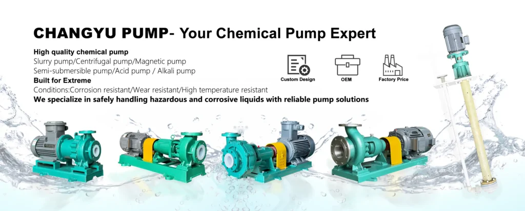
La pompe verticale en fluoroplastique de la série CYL de Changyu Pump offre une solution compacte en ligne pour le transfert de produits chimiques corrosifs dans les secteurs de la transformation chimique, de la galvanoplastie et du traitement de l'eau. Contactez notre équipe d'ingénieurs en fonction des paramètres de votre système et des propriétés du fluide. Nous vous fournirons une recommandation détaillée concernant la pompe ainsi qu'un devis adapté à votre application.