
Jawaban Singkat
Jenis pompa sentrifugal dapat diklasifikasikan berdasarkan empat dimensi utama: berdasarkan jalur fluida melalui impeler (aliran radial, aksial, atau campuran), berdasarkan orientasi mekanis (horizontal atau vertikal), berdasarkan metode penyegelan poros (segel mekanis, kotak isian, atau penggerak magnetik tanpa segel/motor berpendingin), dan berdasarkan standar desain industri (API 610, ISO 2858, atau ANSI B73.1). Memahami dimensi-dimensi ini memungkinkan spesifikasi pompa yang tepat untuk aplikasi industri tertentu. Prinsip klasifikasi utama:
- Desain impeler menentukan karakteristik hidraulik fundamental: Impeler aliran radial menghasilkan head tinggi pada aliran sedang; impeler aliran aksial menghasilkan aliran tinggi pada head rendah; impeler aliran campuran melayani rentang menengah. Kecepatan spesifik impeler (Ns, dalam satuan AS: gpm, ft) adalah parameter pengatur — Ns 7.000 menunjukkan aliran aksial.
- Orientasi mekanis memengaruhi pemasangan dan pemeliharaan: Pompa horizontal memberikan akses yang lebih mudah untuk servis; pompa vertikal meminimalkan jejak dan menghilangkan masalah hisap untuk aplikasi sumur dan sumur dalam.
- Pemilihan metode penyegelan bergantung pada tingkat bahaya fluida: Segel mekanis standar melayani fluida industri umum; segel ganda dan desain tanpa segel (penggerak magnetik, motor berpendingin) ditentukan untuk fluida berbahaya, beracun, atau kemurnian tinggi di mana kebocoran apa pun tidak dapat diterima.
- Standar industri menentukan ketahanan desain: Pompa API 610 menggunakan ketebalan dinding yang lebih besar, bantalan yang lebih besar, dan persyaratan segel yang lebih ketat untuk layanan minyak bumi dan bahaya tinggi. Pompa ISO 2858 dan ANSI B73.1 melayani tugas kimia dan industri umum.
Seorang insinyur pabrik yang meninjau lembar spesifikasi pompa menemukan terminologi yang diambil dari beberapa sistem klasifikasi: “pompa antara bantalan belahan radial API 610 BB2.” Penunjukan tunggal ini merujuk pada standar industri (API 610), konfigurasi mekanis (antara bantalan), dan desain casing (belahan radial). Tanpa memahami kerangka klasifikasi di balik terminologi ini, insinyur tidak dapat mengevaluasi apakah pompa ini — atau alternatif ISO 2858 yang lebih murah — sesuai untuk aplikasi tersebut.
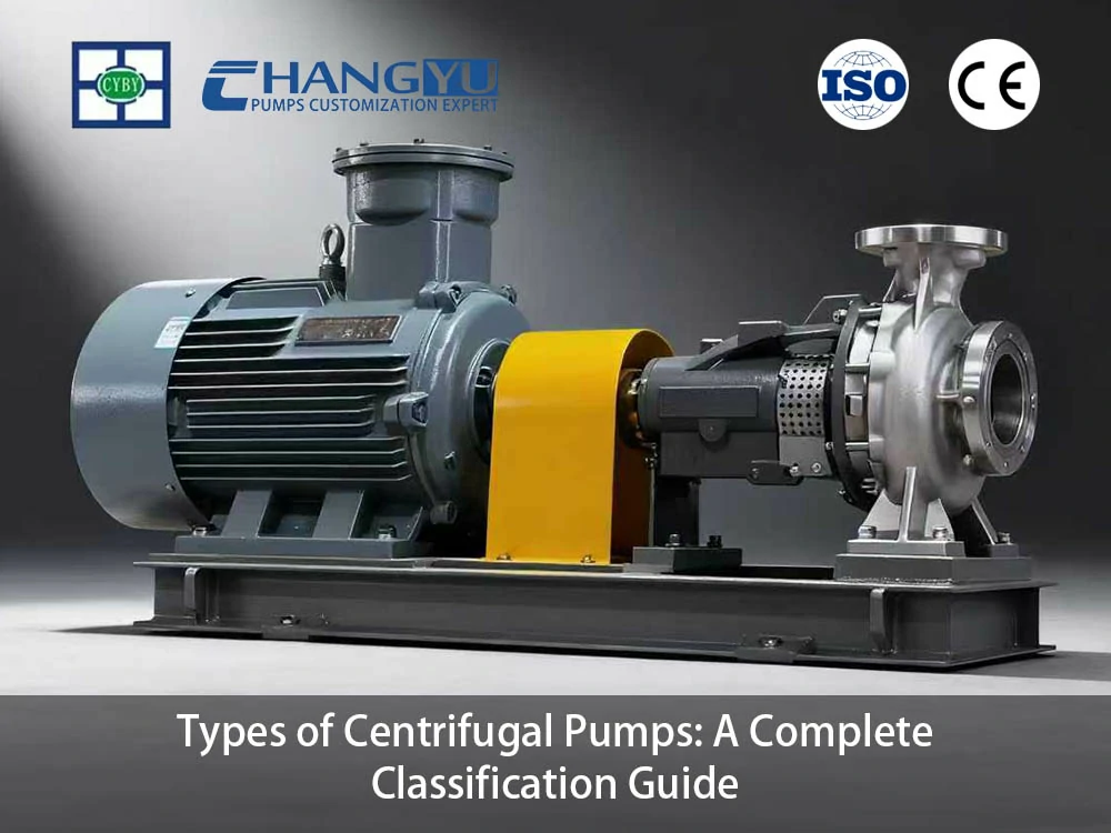
Pompa sentrifugal mendominasi penanganan fluida industri karena satu jenis pompa, melalui variasi geometri impeler, desain casing, dan teknologi penyegelan, dapat melayani aplikasi dari air umpan boiler bertekanan tinggi hingga sirkulasi air pendingin volume tinggi hingga transfer bahan kimia berbahaya. Panduan ini menyediakan kerangka klasifikasi terstruktur — dari jalur aliran impeler hingga standar industri — yang memungkinkan spesifikasi pompa yang tepat.
Bagaimana Pompa Sentrifugal Diklasifikasikan?
Pompa sentrifugal diklasifikasikan berdasarkan empat dimensi independen. Spesifikasi pompa yang lengkap merujuk pada elemen dari setiap dimensi, dan sistem klasifikasi memungkinkan insinyur untuk mencocokkan fitur desain pompa dengan persyaratan aplikasi.
Berdasarkan jalur fluida (geometri impeler): Arah fluida saat keluar dari impeler — radial ke luar, aksial sepanjang poros, atau pada sudut menengah — menentukan karakteristik head-aliran fundamental pompa. Ini adalah klasifikasi hidraulik paling dasar dan dibahas di Bagian 2.
Berdasarkan struktur mekanis (orientasi dan desain casing): Susunan fisik pompa — poros horizontal atau vertikal, rotor overhung atau antara bantalan, casing belahan aksial atau radial — memengaruhi ruang pemasangan, akses pemeliharaan, dan manajemen NPSH. Klasifikasi ini dibahas di Bagian 3.
Berdasarkan metode penyegelan poros: Teknologi yang digunakan untuk menyegel poros berputar di mana ia menembus casing pompa — dari kotak isian sederhana hingga desain penggerak magnetik tanpa segel yang canggih — menentukan risiko kebocoran dan frekuensi pemeliharaan. Klasifikasi ini dibahas di Bagian 4.
Berdasarkan jumlah impeler (staging): Pompa satu tahap mengandung satu impeler dan menghasilkan head sedang. Pompa multi-tahap mengandung beberapa impeler yang disusun secara seri, masing-masing memberikan head tambahan, memungkinkan tekanan pelepasan yang tidak dapat dicapai oleh satu impeler. Klasifikasi ini dibahas di Bagian 5.
Berdasarkan standar desain industri: Industri yang berbeda telah mengembangkan standar pompa spesifik yang mengatur ketebalan dinding, umur desain bantalan, persyaratan segel, dan ketertelusuran material. Tiga standar dominan — API 610, ISO 2858, dan ANSI B73.1 — dibahas di Bagian 6.
Apa Perbedaan Antara Pompa Sentrifugal Aliran Radial, Aksial, dan Campuran?
Arah fluida saat meninggalkan impeler — radial, aksial, atau campuran — adalah klasifikasi hidraulik paling fundamental dari pompa sentrifugal. Karakteristik ini diatur oleh kecepatan spesifik impeler (Ns), parameter tanpa dimensi yang menghubungkan aliran, head, dan kecepatan putar. Jenis impeler pompa sentrifugal didefinisikan oleh parameter tunggal ini.
Prinsip Kecepatan Spesifik
Kecepatan spesifik (Ns, dalam satuan AS: gpm, ft) dihitung dari laju aliran, head, dan kecepatan putar pada titik efisiensi terbaik pompa. Nilai numerik Ns secara langsung menentukan geometri impeler yang optimal:
- Ns < 1.500 (kecepatan spesifik rendah): Impeler aliran radial. Fluida keluar dari impeler tegak lurus terhadap sumbu poros. Impeler ini sempit, dengan diameter luar yang besar relatif terhadap diameter mata. Mereka menghasilkan head tinggi pada aliran yang relatif rendah. Ini adalah jenis impeler yang paling umum untuk pompa proses, pompa umpan boiler, dan aplikasi apa pun yang memerlukan tekanan pelepasan di atas sekitar 50 meter.
- 500 < Ns < 7.000 (kecepatan spesifik sedang): Impeler aliran campuran. Fluida keluar pada sudut antara radial dan aksial. Impeler lebih lebar dari desain radial, dengan diameter mata yang lebih besar. Pompa ini melayani aplikasi head dan aliran menengah — sirkulasi air pendingin, pompa irigasi, dan tugas transfer volume besar.
- Ns > 7.000 (kecepatan spesifik tinggi): Impeller aliran aksial. Fluida keluar sejajar dengan poros, mirip dengan baling-baling kapal. Impeller ini menghasilkan aliran sangat tinggi pada head rendah. Aplikasi meliputi pompa pengendali banjir, pompa angkat air pendingin, dan sirkulasi head rendah.
Catatan: Nilai Ns diberikan dalam satuan AS (gpm, ft). Dalam satuan metrik (m³/s, m), rentang numerik berbeda — bagi nilai AS dengan sekitar 51 untuk konversi.
Perbandingan Jalur Aliran
| Karakteristik | Aliran Radial | Aliran Campuran | Aliran Aksial |
|---|---|---|---|
| Kecepatan spesifik (Ns, satuan AS) | < 1.500 | 500–7.000 | > 7.000 |
| Kemampuan head | Tinggi (50–500+ m) | Sedang (10–50 m) | Rendah (biasanya < 15 m; unit besar dapat mencapai 20 m) |
| Kemampuan aliran | Rendah hingga sedang | Sedang hingga tinggi | Sangat tinggi |
| Bentuk kurva efisiensi | Lebar, datar | Sedang | Sempit, curam |
| Penampilan impeller | Sempit, OD besar | Lebar sedang | Lebar, OD kecil, mirip baling-baling |
| Aplikasi umum | Boiler feed, proses, pipa | Air pendingin, irigasi | Pengendali banjir, angkat air laut |
Para insinyur di Changyu Pump mencatat: Kesalahan spesifikasi umum adalah memilih pompa aliran radial untuk aplikasi aliran tinggi, head rendah. Ketika kecepatan spesifik melebihi sekitar 5.000 (satuan AS), efisiensi impeller radial turun tajam, dan pompa beroperasi dengan risiko tinggi resirkulasi hisap dan kavitasi. Impeller aliran campuran atau aliran aksial bukan alternatif pada rentang ini — keduanya adalah spesifikasi hidraulik yang benar.
Pompa Sentrifugal Horizontal vs Vertikal: Klasifikasi Berdasarkan Struktur Mekanis
Orientasi mekanis pompa sentrifugal — poros horizontal atau vertikal — memengaruhi jejak instalasi, aksesibilitas pemeliharaan, dan hubungan pompa dengan sumber fluida. Pilihan antara konfigurasi horizontal dan vertikal sering ditentukan oleh lokasi pemasangan, bukan oleh karakteristik fluida yang dipompa.
Konfigurasi Pompa Sentrifugal Horizontal
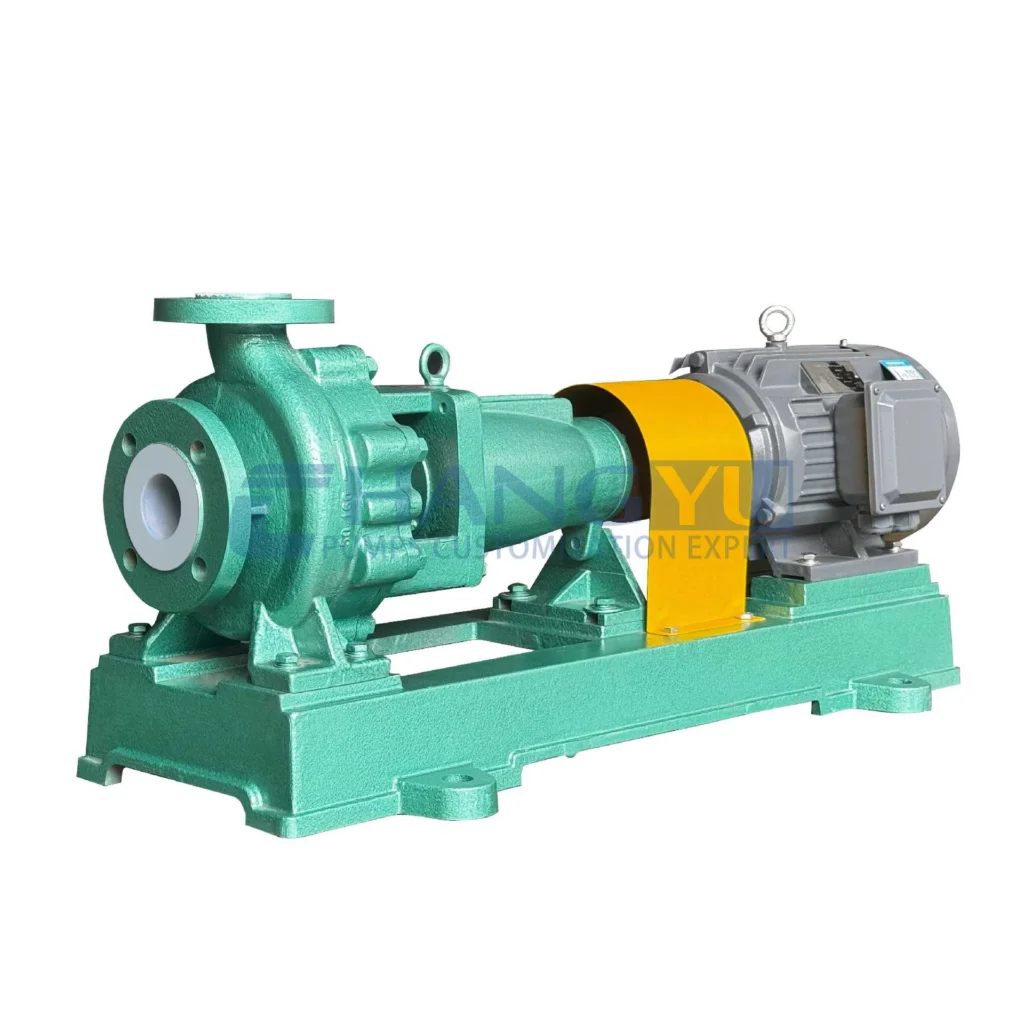
Pompa horizontal memposisikan poros sejajar dengan tanah. Pompa dan penggerak dipasang pada baseplate umum di permukaan tanah, dengan casing pompa dapat diakses dari semua sisi.
- Pompa hisap akhir: Konfigurasi pompa sentrifugal industri paling umum. Fluida masuk melalui nozzle hisap pada sumbu impeller dan keluar secara tegak lurus dari volute. Impeller overhung — dipasang di ujung poros dengan bantalan hanya di satu sisi. Pompa hisap ujung ekonomis, tersedia luas sesuai standar dimensi ISO 2858 dan ANSI B73.1, dan digunakan untuk transfer air umum, kimia, dan cairan bersih.
- Pompa casing terbelah: Casing terbelah secara horizontal (terbelah aksial) atau radial, memungkinkan akses ke impeller dan poros tanpa mengganggu pipa hisap dan buang. Desain antara bantalan mendukung impeller dengan bantalan di kedua sisi, memungkinkan tekanan lebih tinggi dan ukuran lebih besar daripada desain overhung. Pompa casing terbelah aksial adalah standar untuk sirkulasi air pendingin, layanan air pemadam kebakaran, dan pasokan air kota.
- Pompa multistage horizontal: Beberapa impeller dipasang pada poros umum secara seri, masing-masing memberikan head tambahan. Digunakan untuk air umpan boiler, umpan membran reverse osmosis, dan layanan booster pipa yang memerlukan tekanan buang dari 20 bar hingga lebih dari 100 bar.
Konfigurasi Pompa Sentrifugal Vertikal
Pompa vertikal memposisikan poros tegak lurus terhadap tanah. Motor biasanya dipasang di atas pompa, baik langsung di head buang atau di atas pedestal terpisah.
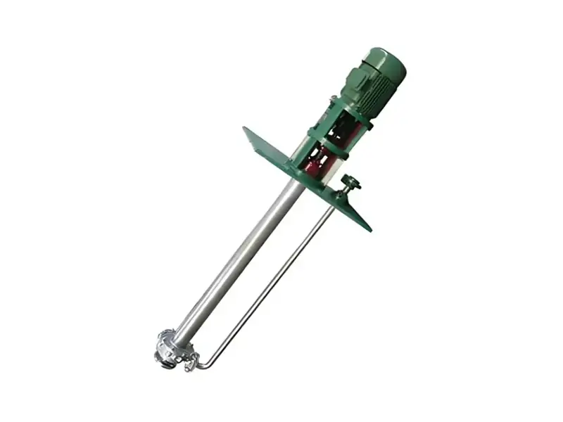
- Pompa turbin vertikal (poros panjang vertikal / pompa sumur dalam): Motor dipasang pada head buang di permukaan tanah, menggerakkan poros yang memanjang ke bawah melalui pipa kolom ke impeller terendam. Beberapa mangkuk impeller dapat ditumpuk secara seri untuk aplikasi head tinggi. Pompa turbin vertikal adalah standar untuk pasokan air sumur dalam, intake air laut, dan angkat air pendingin dari sump dan wet well. Susunan impeller terendam memberikan keunggulan NPSH inheren — pompa tidak dapat kehilangan prime.
- Pompa submersible: Motor dan pompa terintegrasi dalam satu unit tertutup yang dirancang untuk perendaman penuh. Pompa submersible melayani aplikasi sumur dalam, caisson, dan sump di mana pompa poros garis vertikal tidak praktis karena kedalaman atau di mana instalasi harus di bawah permukaan tanah untuk perlindungan banjir.
- Pompa inline vertikal: Desain kompak di mana flange hisap dan buang sejajar pada garis tengah yang sama, memungkinkan pompa dipasang langsung di jalur perpipaan tanpa baseplate. Digunakan untuk layanan gedung, HVAC, dan sirkulasi air industri di mana ruang terbatas.
Matriks Pemilihan Horizontal vs Vertikal
| Faktor | Pompa Horisontal | Pompa Turbin Vertikal | Pompa Inline Vertikal |
|---|---|---|---|
| Luas area pemasangan | Lebih besar — memerlukan baseplate dan rumah pompa | Kecil di permukaan tanah; motor ditinggikan | Minimal — dipasang di jalur pipa |
| Manajemen NPSH | Memerlukan hisap terendam atau perhitungan cermat | Keunggulan inheren — impeller terendam | Memerlukan hisap terendam |
| Akses pemeliharaan | Sangat baik — seluruh pompa di permukaan tanah | Motor dapat diakses; ekstraksi pompa memerlukan crane | Sedang — pompa dapat diakses tetapi terhubung pipa |
| Perlindungan penggerak | Memerlukan penutup cuaca | Motor di atas garis air | Memerlukan penutup cuaca |
| Biaya (relatif) | Lebih rendah | Lebih tinggi — kolom, head buang, sump | Lebih rendah |
| Terbaik untuk | Industri umum, proses, transfer | Sumur dalam, sump, intake air laut | Layanan gedung, HVAC |
Pompa Sentrifugal Mechanical Seal vs Sealless: Klasifikasi Berdasarkan Metode Penyegelan Poros
Metode penyegelan poros adalah dimensi klasifikasi kritis untuk pompa sentrifugal dalam layanan berbahaya, korosif, atau kemurnian tinggi. Seal mencegah fluida yang dipompa keluar di sepanjang poros berputar di mana poros menembus casing pompa. Pilihan teknologi penyegelan secara langsung memengaruhi kepatuhan lingkungan, keselamatan operator, dan frekuensi pemeliharaan.
Opsi Teknologi Penyegelan
Gland terkemas (packing kompresi) : Cincin packing anyaman dikompresi di sekitar poros oleh pengikut gland memberikan seal poros paling dasar. Packing memerlukan kebocoran terkontrol kecil — biasanya 30–60 tetes per menit — untuk melumasi dan mendinginkan antarmuka packing-poros. Gland terkemas toleran terhadap padatan dan ketidaksejajaran tetapi memerlukan penyesuaian berkala — mingguan hingga triwulanan tergantung kondisi layanan. Digunakan pada pompa slurry, pompa air limbah, dan aplikasi di mana kebocoran kecil dapat diterima.
Segel mekanis tunggal: Rakitan segel presisi yang terdiri dari permukaan stasioner yang dipasang di rumah pompa dan permukaan berputar yang dipasang pada poros, ditahan bersentuhan oleh pegas. Lapisan film fluida mikroskopis di antara permukaan segel memberikan pelumasan dan pendinginan. Segel tunggal memberikan kebocoran terlihat hampir nol dalam kondisi operasi normal tetapi tidak memiliki cadangan jika permukaan segel primer gagal. Segel ini menjadi standar untuk transfer air industri umum dan kimia.
Segel mekanis ganda: Dua dengan ruang oli di antara keduanya — oli memberikan pelumasan dan dapat dipantau untuk masuknya air, memberikan peringatan dini kegagalan segel bawah. disusun saling membelakangi atau secara tandem, dengan fluida penghalang yang disirkulasikan di antara keduanya pada tekanan lebih tinggi daripada fluida yang dipompa. Pengaturan ini memberikan penahanan positif — jika segel dalam bocor, fluida penghalang masuk ke pompa; segel luar mencegah kebocoran ke atmosfer. Segel ganda ditentukan untuk fluida berbahaya, mudah terbakar, atau beracun di mana pelepasan ke atmosfer tidak dapat diterima.
Pompa penggerak magnetik tanpa seal: Impeler dipasang pada poros yang didukung oleh bantalan yang dilumasi produk di dalam cangkang penahanan tertutup. Rakitan magnet luar yang digabungkan ke poros motor menggerakkan rakitan magnet dalam melalui dinding cangkang penahanan — tidak ada penetrasi poros dinamis. Pompa penggerak magnetik menghilangkan segel mekanis sepenuhnya, memberikan kebocoran nol. Segel ini ditentukan untuk bahan kimia berisiko tinggi, fluida perpindahan panas, dan aplikasi di mana perawatan segel tidak praktis.
Pompa motor tertutup (canned motor pump): Mirip dengan pompa penggerak magnetik, tetapi rotor motor itu sendiri beroperasi terendam dalam fluida yang dipompa di dalam cangkang penahanan tertutup. Stator motor berada di luar cangkang. Pompa motor berpendingin menghilangkan segel poros dan motor eksternal, memberikan konfigurasi tanpa segel yang paling ringkas. Pompa ini digunakan untuk aplikasi tekanan tinggi di mana batas torsi kopling magnetik akan terlampaui, dan untuk layanan suhu tinggi.
Panduan Pemilihan Metode Penyegelan
| Metode Penyegelan | Risiko Kebocoran | Jadwal Perawatan | Biaya Relatif | Terbaik untuk |
|---|---|---|---|---|
| Kotak isian terkompresi | Kebocoran terkendali dapat diterima | Berkala — mingguan hingga triwulanan tergantung pada layanan | $ | Lumpur, air limbah, fluida yang mengandung padatan |
| Segel mekanis tunggal | Kebocoran terlihat hampir nol | 12–24 bulan | $$ | Industri umum, fluida bersih |
| Segel mekanis ganda | Tidak ada — penahanan positif | 12–24 bulan | $$$ | Fluida berbahaya, mudah terbakar, beracun |
| Penggerak magnetik | Tidak ada — tanpa segel | 24–36 bulan (bantalan) | $$$$ | Bahan kimia berisiko tinggi, fluida perpindahan panas |
| Motor kaleng | Tidak ada — tanpa segel | 24–36 bulan (bantalan) | $$$$$ | Tanpa segel tekanan tinggi, suhu tinggi |
Pompa Sentrifugal Satu Tahap vs Multi-Tahap: Klasifikasi Berdasarkan Jumlah Impeler
Jumlah impeler dalam pompa sentrifugal — satu atau banyak — menentukan kemampuan menghasilkan tekanan. Klasifikasi ini independen dari jalur aliran, struktur mekanis, dan metode penyegelan yang dibahas di atas. Pompa multi-tahap dapat berupa aliran radial, horizontal, dan tersegel mekanis, sama seperti pompa satu tahap.
Pompa satu tahap mengandung satu impeler dan satu volute atau diffuser. Impeler harus menghasilkan seluruh tekanan pembuangan yang diperlukan dalam satu lintasan. Batas praktis untuk pompa sentrifugal satu tahap sekitar 150–200 meter head, tergantung pada diameter impeler dan kecepatan putaran. Di luar rentang ini, tegangan impeler dan keterbatasan hidrolik membuat satu tahap tidak praktis. Pompa satu tahap melayani mayoritas aplikasi industri: transfer air, sirkulasi kimia, air pendingin, dan tugas proses umum.
Pompa sentrifugal multi-tahap mengandung dua atau lebih impeler yang disusun secara seri pada poros yang sama. Fluida yang dibuang dari impeler pertama masuk ke hisapan impeler kedua, dan setiap impeler berikutnya memberikan tambahan head. Pompa dua tahap secara efektif menggandakan kemampuan tekanan dari desain satu tahap menggunakan diameter impeler yang sama. Pompa multi-tahap dengan 4–12 tahap secara rutin menghasilkan tekanan pembuangan 40–100 bar, dan pompa pengumpan boiler khusus dengan 20+ tahap mencapai 200 bar dan lebih.
Trade-off untuk kemampuan multi-tahap adalah peningkatan biaya, kompleksitas, dan manajemen dorongan aksial. Setiap tahap tambahan menambah panjang, berat, dan beban bantalan pompa. Pompa multi-tahap juga memerlukan perlindungan aliran minimum — beroperasi pada kondisi tertutup atau aliran sangat rendah dapat menyebabkan panas berlebih dan kerusakan dengan cepat.
Pemilihan Satu Tahap vs Multi-Tahap:
| Faktor | Pompa Satu Tahap | Pompa Multi-Tahap |
|---|---|---|
| Kemampuan head | Hingga ~150–200 m | 40–200+ bar |
| Kompleksitas mekanis | Rendah | Sedang hingga tinggi |
| Biaya (relatif) | Lebih rendah | Lebih tinggi |
| Perlindungan aliran minimum | Standar | Kritis — resirkulasi diperlukan |
| Terbaik untuk | Industri umum, transfer, sirkulasi | Pengumpan boiler, pengumpan RO, booster pipa, transfer jarak jauh |
Pompa Sentrifugal API vs ISO vs ANSI: Klasifikasi Berdasarkan Standar Industri
Tiga standar desain dominan mengatur konstruksi pompa sentrifugal untuk berbagai industri dan pasar geografis. Pompa yang dibangun sesuai standar yang berbeda tidak dapat dipertukarkan secara dimensional dan menggabungkan filosofi desain yang berbeda secara fundamental mengenai ketahanan dan keandalan.
API 610 (Institut Perminyakan Amerika) : Standar untuk pompa sentrifugal di industri minyak bumi, petrokimia, dan gas alam. Pompa API 610 dirancang untuk layanan kontinu dengan keandalan tinggi untuk fluida berbahaya, mudah terbakar, dan bersuhu tinggi. Fitur desain utama meliputi: kelonggaran korosi minimum 3 mm pada casing; umur bantalan L10 25.000 jam pada kondisi terukur untuk pompa layanan kontinu (16.000 jam untuk pompa layanan intermiten); sistem segel mekanis API 682 dengan rencana pembilasan komprehensif; dan pengujian hidrostatik serta kinerja penuh dengan kurva bersertifikat.
ISO 2858 (Organisasi Internasional untuk Standardisasi) : Standar internasional untuk pompa sentrifugal hisapan ujung yang digunakan dalam layanan kimia dan industri umum. ISO 2858 mendefinisikan pertukaran dimensional — pompa dari berbagai produsen dapat saling menggantikan tanpa modifikasi pipa atau pelat dasar. Pompa ISO dirancang untuk layanan kimia tugas sedang dengan material tahan korosi tetapi tidak menggabungkan konstruksi dinding tebal atau umur bantalan yang diperpanjang dari pompa API 610.
ANSI B73.1 (Institut Standar Nasional Amerika) : Standar AS untuk pompa sentrifugal hisapan ujung horizontal untuk layanan proses kimia. Secara fungsional serupa dengan ISO 2858 dalam cakupan aplikasi, tetapi tidak kompatibel secara dimensi — pompa ANSI menggunakan dimensi inci sementara pompa ISO menggunakan metrik. Pompa ANSI mendominasi pasar kimia Amerika Utara.
Perbandingan Standar Industri
| Fitur Desain | API 610 | ISO 2858 | ANSI B73.1 |
|---|---|---|---|
| Ketebalan dinding casing | Berat — kelonggaran korosi minimum 3 mm | Standar — kelonggaran korosi 1,5–2 mm | Standar |
| Umur bantalan L10 | 000 jam (kontinu); 16.000 jam (intermiten) | 500 jam tipikal | 500 jam tipikal |
| Persyaratan seal | API 682 — rencana flush komprehensif | Segel mekanis standar | Segel mekanis standar |
| Uji hidrostatik | 1,5× tekanan desain | 1,3× tekanan desain | 1,3× tekanan desain |
| Biaya relatif | 2–3× ISO/ANSI (lebih tinggi untuk pompa kecil, lebih rendah untuk pompa besar) | 1× (dasar) | 1× (dasar) |
| Pasar utama | Minyak & gas, petrokimia | Kimia global, industri umum | Kimia Amerika Utara |
Para insinyur di Changyu Pump mencatat: Pompa API 610 sering kali di-spesifikasi berlebihan untuk aplikasi industri umum berisiko rendah — kesalahan yang mahal yang didorong oleh asumsi bahwa “API berarti lebih baik.” Meskipun pompa API 610 memiliki konstruksi yang lebih berat dan umur bantalan desain yang lebih panjang, fitur-fitur ini hanya dibenarkan ketika fluida yang dipompa berbahaya, mudah terbakar, atau bersuhu tinggi, atau ketika proses beroperasi secara kontinu tanpa pompa cadangan. Untuk layanan kimia dan industri umum, pompa ISO 2858 atau ANSI B73.1 memberikan keandalan yang sesuai dengan biaya modal yang jauh lebih rendah. API 610 harus di-spesifikasi ketika kondisi proses menuntut fitur desainnya — bukan sebagai pilihan default.
Bagaimana Memilih Jenis Pompa Sentrifugal yang Tepat untuk Aplikasi Anda?
Sistem klasifikasi yang dijelaskan di Bagian 2 hingga 6 bertemu dalam proses pemilihan pompa. Spesifikasi yang benar mensyaratkan penanganan setiap dimensi klasifikasi secara berurutan, dimulai dengan kebutuhan hidraulik dan dilanjutkan melalui pertimbangan mekanis dan sealing.
Matriks Pemilihan Berbasis Aplikasi
| Aplikasi | Jenis Impeler yang Direkomendasikan | Konfigurasi | Metode Penyegelan | Standar Tipikal |
|---|---|---|---|---|
| Air umpan boiler | Radial, multi-tahap | Horizontal antara bantalan | Segel mekanis tunggal atau ganda | API 610 |
| Sirkulasi air pendingin | Aliran campuran atau radial | Split case horizontal atau turbin vertikal | Packed gland atau seal tunggal | ISO 2858 |
| Air pemadam kebakaran | Radial | Split case horizontal atau turbin vertikal | Kotak isian terkompresi | API 610 / NFPA 20 |
| Transfer kimia | Radial | Hisapan ujung horizontal | Seal tunggal atau ganda; penggerak magnetik untuk fluida berbahaya | ISO 2858 / ANSI B73.1 |
| Pasokan air kota | Radial, multi-tahap | Split case horizontal atau turbin vertikal | Packed gland atau seal tunggal | ISO 2858 |
| Air sumur dalam | Campuran atau radial | Turbin vertikal atau submersible | Tidak berlaku (terendam) | ISO 2858 / AWWA |
| Intake air laut | Aliran campuran atau aksial | Turbin vertikal | Packed gland atau seal tunggal | API 610 / ISO 2858 |
Urutan Pemilihan
Langkah 1: Tentukan kebutuhan hidraulik. Hitung laju aliran dan total head dinamis. Pilih jalur aliran impeler (radial, campuran, atau aksial) berdasarkan kecepatan spesifik dan kombinasi head-aliran. Langkah ini menetapkan desain hidraulik fundamental pompa.
Langkah 2: Pilih konfigurasi mekanis. Pilih orientasi horizontal atau vertikal berdasarkan ruang instalasi, ketersediaan NPSH, dan akses pemeliharaan. Untuk aplikasi sumur dalam atau bak penampung, vertikal biasanya diperlukan. Untuk instalasi di tingkat permukaan dengan hisapan terisi penuh, horizontal lebih disukai.
Langkah 3: Tentukan metode sealing. Sesuaikan teknologi seal dengan tingkat bahaya fluida. Packed gland untuk slurry dan air limbah yang tidak berbahaya. Mechanical seal tunggal untuk fluida industri umum. Seal ganda atau desain tanpa seal untuk fluida berbahaya, beracun, atau kemurnian tinggi.
Langkah 4: Pilih tahapan (tunggal atau multi-tahap). Jika total head melebihi sekitar 150 meter, multi-tahap diperlukan. Di bawah ambang batas ini, tahap tunggal lebih ekonomis kecuali head mendekati batas atas kemampuan tahap tunggal.
Langkah 5: Terapkan standar industri yang sesuai. API 610 untuk layanan minyak bumi, petrokimia, dan bahaya tinggi. ISO 2858 atau ANSI B73.1 untuk aplikasi kimia dan industri umum.
Untuk panduan aplikasi spesifik tentang air laut, slurry, dan jenis pompa sekrup industri, lihat panduan kami tentang Pompa Air Laut: Panduan Pemilihan, Material & Aplikasi, Pompa Slurry di Pertambangan: Cara Memilih Pompa Kelas Tambang yang Tepat, dan Pompa Sekrup Industri: Panduan Jenis, Pemilihan, dan Aplikasi.
Para insinyur di Changyu Pump mencatat: Kesalahan pemilihan pompa sentrifugal yang paling umum adalah spesifikasi berdasarkan aliran dan head saja, mengabaikan kecepatan spesifik dan jalur aliran impeler. Pompa yang dipilih hanya berdasarkan kurva head-aliran dapat beroperasi pada efisiensi buruk, getaran tinggi, dan biaya pemeliharaan yang meningkat jika geometri impeler tidak cocok dengan kebutuhan hidraulik aplikasi. Selalu verifikasi bahwa kecepatan spesifik pompa berada dalam rentang yang direkomendasikan untuk tugas yang dimaksud sebelum finalisasi spesifikasi.
Studi Kasus: Bagaimana Pompa yang Salah Klasifikasi Menyebabkan Penghentian Pabrik
Sebuah pabrik kimia di Asia Tenggara memasang pompa sentrifugal hisapan ujung tahap tunggal ISO 2858 untuk memasok air umpan boiler ke boiler paket. Pompa di-spesifikasi berdasarkan laju aliran saja, dengan asumsi bahwa pompa hisapan ujung standar akan memberikan tekanan yang cukup. Boiler membutuhkan head 150 meter di saluran masuk air umpan. Pompa tahap tunggal, dengan head terukur sekitar 50 meter, tidak dapat mengatasi tekanan drum boiler.
Dalam minggu pertama komisioning, boiler mengalami trip air rendah selama permintaan puncak. Pompa air umpan beroperasi pada head penutupan — tekanan maksimum yang dapat dihasilkan — dan hanya mengirimkan sebagian kecil dari aliran yang dibutuhkan. Dua trip boiler dalam satu bulan menghasilkan sekitar 12 jam total waktu henti produksi.
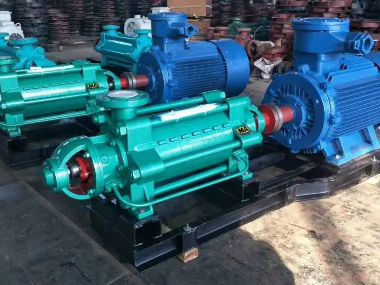
Changyu Pump mengganti pompa tahap tunggal dengan pompa sentrifugal multi-tahap horizontal — desain aliran radial dengan empat impeler secara seri, masing-masing memberikan sekitar 40 meter head untuk total head terukur 160 meter. Konfigurasi multi-tahap memberikan tekanan pelepasan yang diperlukan dengan aliran stabil di seluruh rentang operasi boiler.
Selama 24 bulan operasi setelah penggantian: tidak ada trip air umpan boiler. Pompa beroperasi dalam rentang aliran yang direkomendasikan sepanjang siklus permintaan modulasi boiler. Biaya awal pompa multi-tahap yang lebih tinggi dipulihkan dalam enam bulan pertama melalui penghapusan waktu henti produksi.
Poin penting: Klasifikasi pompa bukanlah latihan akademis. Menentukan pompa satu tahap untuk aplikasi multi-tahap — atau pompa aliran radial untuk tugas aliran aksial — secara langsung menyebabkan kegagalan peralatan dan kehilangan produksi. Memahami dimensi klasifikasi dalam panduan ini memungkinkan pemilihan pompa yang tepat sebelum instalasi, di mana biaya koreksi paling rendah.
FAQ tentang Jenis-Jenis Pompa Sentrifugal
T: Apa saja jenis utama pompa sentrifugal?
J: Pompa sentrifugal diklasifikasikan berdasarkan jalur aliran impeler (radial, campuran, aksial), struktur mekanis (horizontal, vertikal), metode penyegelan poros (segel mekanis, kelenjar kemasan, penggerak magnetik tanpa segel, motor canned), jumlah tahap (satu atau multi-tahap), dan standar desain industri (API 610, ISO 2858, ANSI B73.1).
T: Apa perbedaan antara pompa sentrifugal aliran radial dan aliran aksial?
J: Impeler aliran radial mengeluarkan fluida tegak lurus terhadap poros dan menghasilkan head tinggi pada aliran rendah hingga sedang. Impeler aliran aksial mengeluarkan fluida sejajar dengan poros dan menghasilkan aliran tinggi pada head rendah. Kecepatan spesifik (Ns, dalam satuan AS: gpm, ft) menentukan geometri impeler yang optimal.
T: Kapan saya harus memilih pompa vertikal daripada pompa horizontal?
J: Pilih pompa vertikal ketika sumber fluida berada di bawah pompa — sumur dalam, bak penampung, atau saluran masuk air laut. Pompa turbin vertikal juga lebih disukai ketika ruang instalasi di permukaan tanah terbatas atau motor harus dinaikkan di atas tingkat banjir.
T: Apa perbedaan antara pompa API 610 dan ISO 2858?
J: Pompa API 610 memiliki ketebalan dinding yang lebih berat, bantalan yang lebih besar dengan peringkat umur L10 minimum 25.000 jam (duty kontinu), dan persyaratan segel yang lebih ketat. Pompa ini ditentukan untuk layanan minyak bumi dan bahaya tinggi. Pompa ISO 2858 adalah pompa proses kimia standar dengan pertukaran dimensi antar produsen.
T: Kapan saya harus menggunakan pompa penggerak magnetik daripada pompa bersegel mekanis?
J: Pompa penggerak magnetik menghilangkan segel poros dinamis dan ditentukan untuk fluida berbahaya, beracun, atau kemurnian tinggi di mana kebocoran apa pun tidak dapat diterima, atau di mana perawatan segel tidak praktis karena lokasi terpencil atau persyaratan operasi kontinu.
T: Bagaimana saya tahu apakah saya memerlukan pompa satu tahap atau multi-tahap?
J: Jika total head pelepasan yang dibutuhkan melebihi sekitar 150–200 meter, pompa multi-tahap diperlukan. Di bawah ambang batas ini, pompa satu tahap biasanya lebih ekonomis. Pompa multi-tahap juga ditentukan ketika head mendekati batas atas kemampuan satu tahap dan aliran stabil di seluruh rentang operasi yang luas diperlukan.
Daftar Periksa Pencegahan untuk Insinyur Pompa Changyu
- Tentukan kecepatan spesifik (Ns) sebelum memilih jenis impeler. Gunakan satuan AS (gpm, ft) untuk perhitungan. Pompa yang ditentukan hanya berdasarkan aliran dan head dapat beroperasi pada efisiensi yang buruk jika geometri impeler tidak sesuai dengan kebutuhan hidraulik.
- Jangan menentukan pompa aliran radial untuk aplikasi aliran tinggi dan head rendah. Ketika Ns melebihi sekitar 5.000 (satuan AS), impeler aliran campuran atau aliran aksial adalah spesifikasi hidraulik yang benar.
- Pilih metode penyegelan poros berdasarkan tingkat bahaya fluida — bukan berdasarkan biaya awal. Pompa penggerak magnetik atau segel mekanis ganda untuk fluida berbahaya. Segel tunggal untuk layanan industri umum. Kelenjar kemasan untuk lumpur dan air limbah.
- Jangan secara default menggunakan API 610 untuk aplikasi industri umum. Pompa API 610 berbiaya 2–3× lebih mahal daripada setara ISO 2858 (lebih tinggi untuk pompa kecil, lebih rendah untuk pompa besar). Tentukan API 610 hanya ketika kondisi proses menuntut fitur desainnya — fluida berbahaya, suhu tinggi, operasi kontinu tanpa pompa cadangan.
- Pilih konfigurasi pompa turbin vertikal ketika sumber fluida berada di bawah pompa. Pompa turbin vertikal menghilangkan masalah hisap angkat dan mengakomodasi fluktuasi tingkat air di bak penampung, sumur, dan struktur intake.
- Verifikasi bahwa NPSH yang dibutuhkan pompa (NPSHr) setidaknya 1 meter di bawah NPSH yang tersedia sistem (NPSHa) di semua kondisi operasi. Margin ini memperhitungkan variasi suhu fluida, tingkat hisap, dan laju aliran.
- Untuk pompa multi-tahap, pastikan jalur bypass aliran minimum atau jalur resirkulasi terpasang. Mengoperasikan pompa multi-tahap pada atau mendekati kondisi shut-off menyebabkan panas berlebih dan kerusakan dengan cepat.
- Saat mengganti pompa yang ada, verifikasi standar dimensi (ISO 2858, ANSI B73.1, atau API 610). Pompa ISO dan ANSI tidak dapat dipertukarkan secara dimensi — standar yang berbeda akan memerlukan modifikasi perpipaan dan pelat dasar.
Kesimpulan
Klasifikasi pompa sentrifugal adalah sistem terstruktur yang memungkinkan para insinyur untuk mencocokkan fitur desain pompa dengan persyaratan aplikasi di berbagai dimensi independen. Jalur aliran impeler — radial, aksial, atau campuran — menentukan karakteristik head-aliran fundamental pompa dan diatur oleh kecepatan spesifik (Ns, dalam satuan AS). Orientasi mekanis — horizontal atau vertikal — memengaruhi instalasi, perawatan, dan manajemen NPSH. Metode penyegelan poros — dari kelenjar kemasan hingga penggerak magnetik tanpa segel — menentukan risiko kebocoran dan frekuensi perawatan. Jumlah tahap — satu atau multi — menentukan kemampuan tekanan. Dan standar desain industri — API 610, ISO 2858, atau ANSI B73.1 — menentukan ketahanan desain dan pertukaran dimensi pompa. Spesifikasi pompa yang benar memerlukan penanganan setiap dimensi ini secara berurutan, dimulai dengan kebutuhan hidraulik dan dilanjutkan melalui pertimbangan mekanis, penyegelan, tahapan, dan standar.
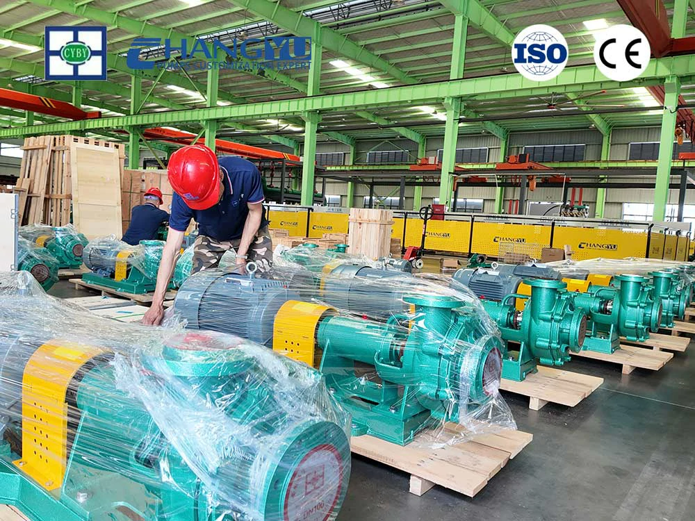
Tim teknik Changyu Pump menyediakan panduan klasifikasi dan pemilihan pompa yang spesifik untuk aplikasi, didukung oleh lebih dari 20 tahun pengalaman manufaktur pompa sentrifugal di seluruh spektrum aplikasi industri.