
Jawaban Singkat
A pompa sentrifugal memindahkan fluida dengan mengubah energi kinetik rotasional dari impeler menjadi kecepatan fluida, kemudian menjadi tekanan di volute. Pada titik efisiensi terbaiknya (BEP), pompa sentrifugal industri yang diukur dengan tepat mengubah 75–90% daya input motor menjadi daya fluida — pompa yang lebih kecil (di bawah 5 kW) biasanya mencapai 50–70%. Beroperasi di luar BEP dapat membuang energi secara signifikan setiap tahunnya. Proses ini mengikuti empat langkah: fluida masuk ke mata impeler, impeler yang berputar melemparkan fluida ke luar dengan gaya sentrifugal, fluida memperoleh kecepatan dan tekanan, dan volute mengubah sisa kecepatan menjadi tekanan discharge yang dapat digunakan.
Pompa sentrifugal adalah jenis pompa yang paling banyak digunakan dalam penanganan fluida industri, memindahkan segala sesuatu mulai dari air bersih hingga bahan kimia korosif. Baik dalam pasokan air kota, sistem HVAC, pemrosesan kimia, atau pabrik desalinasi, prinsip dasar yang sama berlaku: impeler yang berputar menciptakan gaya yang menggerakkan fluida melalui sistem.
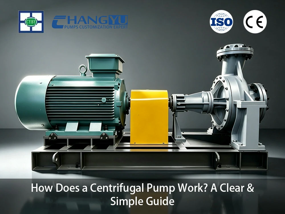
Panduan ini menjelaskan cara kerja pompa sentrifugal — dari prinsip dasar dan komponen utama hingga kurva kinerja dan kavitasi — secara jelas dan praktis. Tidak diperlukan pengetahuan pompa sebelumnya.
Istilah Kunci Pompa Sentrifugal Sekilas
Tabel: Istilah Kunci Pompa Sentrifugal Sekilas
| Istilah | Definisi |
|---|---|
| Baling-baling | Komponen berputar dengan sudu melengkung yang mentransfer energi ke fluida |
| Volute | Rumah spiral yang mengumpulkan fluida dari impeler dan mengubah kecepatan menjadi tekanan |
| BEP (Titik Efisiensi Terbaik) | Laju aliran di mana pompa beroperasi pada efisiensi hidraulik maksimum |
| Kavitasi | Pembentukan dan runtuhnya gelembung uap di dalam pompa, menyebabkan kebisingan, getaran, dan kerusakan impeler |
| NPSH (Tinggi Isap Positif Net) | Margin tekanan yang diperlukan pada sisi hisap pompa untuk mencegah kavitasi |
| Kepala | Ketinggian yang dapat diangkat oleh pompa untuk mengangkat fluida, dinyatakan dalam meter atau kaki kolom cairan |
| Segel Mekanis | Komponen penyegel yang mencegah kebocoran fluida di sepanjang poros yang berputar |
Bagaimana Cara Kerja Pompa Sentrifugal? Prinsip Sederhana
The pompa sentrifugal Prinsip kerja dapat dipahami dalam empat langkah, masing-masing sesuai dengan apa yang terjadi pada fluida saat melewati pompa.
Langkah 1: Fluida Masuk ke Mata Impeler
Fluida masuk ke pompa melalui nosel hisap dan mengalir ke pusat impeler — yang disebut mata impeler. Impeler adalah piringan berputar dengan sudu melengkung, dipasang pada poros yang digerakkan oleh motor listrik atau mesin. Pada titik ini, fluida memiliki kecepatan dan tekanan yang relatif rendah — fluida hanya ditarik masuk oleh putaran impeler.
Langkah 2: Impeler Mempercepat Fluida
Saat impeler berputar (biasanya pada 1.450–3.600 r/min), sudu melengkung menangkap fluida dan melemparkannya ke luar dengan gaya sentrifugal. Ini adalah gaya yang sama yang Anda rasakan saat mengayunkan ember berisi air dalam lingkaran — air didorong ke luar menuju dinding ember. Di dalam pompa, sudu impeler mempercepat fluida dari pusat ke tepi luar, secara dramatis meningkatkan kecepatannya.
Pada keluaran impeler, fluida telah memperoleh energi kinetik (kecepatan) yang signifikan dan sebagian tekanan. Konversi daya poros mekanis menjadi energi fluida ini adalah fungsi inti dari impeler.
Langkah 3: Volute Mengubah Kecepatan menjadi Tekanan
Fluida yang meninggalkan impeler masuk ke volute — rumah berbentuk spiral yang mengelilingi impeler. Saluran volute secara bertahap melebar saat melingkari impeler. Pelebaran saluran ini berfungsi seperti jalan keluar jalan tol: saat jalur melebar, lalu lintas melambat tetapi menjadi lebih padat. Demikian pula, saat penampang volute meningkat, kecepatan fluida menurun dan energi kinetik berubah menjadi energi tekanan.
Konversi ini sangat penting karena sebagian besar aplikasi industri membutuhkan tekanan (untuk mengatasi gesekan pipa, mengangkat fluida ke ketinggian, atau memaksanya melalui filter) daripada kecepatan mentah.
Langkah 4: Fluida Dibuang
Di ujung volute, fluida mencapai nosel discharge pada tekanan dan laju aliran terukur pompa. Fluida kini telah menyelesaikan perjalanannya melalui pompa — masuk pada tekanan dan kecepatan rendah, dan keluar pada tekanan tinggi dengan aliran yang terkendali. Proses berkelanjutan ini berulang selama impeler berputar dan fluida disuplai ke sisi hisap.
Singkatnya: impeler menambahkan kecepatan; volute mengubah kecepatan menjadi tekanan. Konversi energi dua tahap inilah yang mendefinisikan pompa sentrifugal.
Apa Saja Bagian Utama dari Pompa Sentrifugal?
Pompa sentrifugal terdiri dari komponen yang relatif sedikit, tetapi masing-masing memainkan peran spesifik dalam menggerakkan dan mengendalikan fluida. Memahami bagian-bagian ini membuat pemilihan pompa dan pemecahan masalah menjadi jauh lebih intuitif.
Lima Komponen Esensial
Impeller:
Impeler adalah komponen kerja utama dari pompa sentrifugal. Ini adalah piringan berputar dengan sudu melengkung yang mentransfer energi mekanis dari poros motor ke
fluida. Impeler tersedia dalam beberapa desain: tertutup (dengan shroud depan dan belakang untuk efisiensi maksimum dengan fluida bersih), semi-terbuka (dengan shroud belakang saja, untuk fluida dengan beberapa padatan), dan terbuka (tanpa shroud, untuk fluida kental atau yang mengandung padatan). Diameter impeler dan geometri sudu menentukan laju aliran dan kemampuan head pompa.
Volute (Rumah):
Volute adalah rumah stasioner yang mengelilingi impeler. Bentuk spiralnya sangat penting — luas penampang yang meningkat secara bertahap mengubah fluida berkecepatan tinggi yang meninggalkan impeler menjadi tekanan yang dapat digunakan di discharge. Volute juga mengumpulkan fluida dari impeler dan mengarahkannya ke nosel discharge. Dalam beberapa desain pompa, diffuser (cincin sudu stasioner) digunakan sebagai pengganti atau tambahan untuk volute untuk pemulihan tekanan yang lebih terkendali.
Poros dan Bantalan:
Poros menghubungkan impeler ke motor dan mentransmisikan daya rotasional. Poros harus dikerjakan dengan presisi dan diluruskan untuk meminimalkan getaran. Bantalan mendukung poros, memungkinkannya berputar bebas sambil menyerap beban radial dan aksial dari impeler. Bantalan tugas berat yang diperbesar ditentukan untuk pompa industri dengan operasi kontinu.
Segel Mekanis:
The segel mekanis adalah komponen penting yang mencegah kebocoran fluida di sepanjang poros berputar di titik keluar dari rumah pompa. Komponen ini terdiri dari dua permukaan datar — satu berputar dengan poros, satu diam di rumah pompa — yang ditekan bersama oleh pegas. Lapisan fluida mikroskopis di antara permukaan tersebut memberikan pelumasan dan pendinginan. Mechanical seal standar menangani fluida bersih yang tidak mengkristal; double seal atau sistem flush seal diperlukan untuk fluida abrasif, korosif, atau yang mengkristal. Untuk aplikasi yang menuntut, sistem flush seal eksternal memberikan pendinginan dan mencegah padatan mencapai permukaan seal.
Nozel Hisap dan Pelepasan:
Nozzle hisap terhubung ke pipa masuk dan mengalirkan fluida ke mata impeller. Nozzle discharge terhubung ke pipa keluar di outlet volute. Ukuran dan orientasi nozzle ini menentukan bagaimana pompa terintegrasi ke dalam sistem perpipaan.
Ringkasan Komponen Utama
Tabel: Komponen Utama Pompa Sentrifugal
| Komponen | Fungsi | Bahan Umum |
|---|---|---|
| Baling-baling | Mentransfer energi mekanik ke fluida | Besi cor, 316L SS, Duplex 2205, paduan high-chrome |
| Volute / Rumah Pompa | Mengubah kecepatan menjadi tekanan | Besi cor, besi ulet, 316L SS, dilapisi FEP/PFA |
| Poros | Mentransmisikan daya motor ke impeller | Baja paduan kekuatan tinggi, 316L SS |
| Bantalan | Mendukung rotasi poros; menyerap beban | Bantalan bola atau rol dengan pelumas gemuk |
| Segel Mekanis | Mencegah kebocoran di sepanjang poros | Permukaan karbon vs. keramik atau tungsten karbida; O-ring EPDM, FKM, atau PTFE |
Cara Membaca Kurva Kinerja Pompa Sentrifugal dan Menghindari Kesalahan yang Mahal
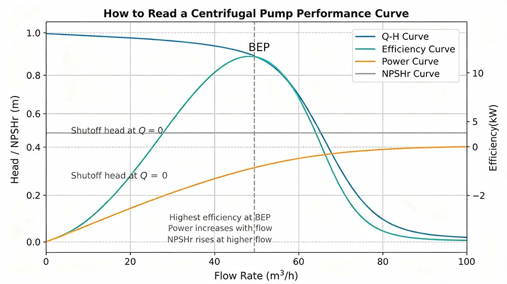
Kurva kinerja pompa sentrifugal adalah grafik yang menunjukkan bagaimana pompa berperilaku pada berbagai laju aliran. Mempelajari cara membaca kurva ini sangat penting untuk memilih pompa yang tepat dan menghindari kesalahan operasional yang mahal.
Empat Kurva pada Bagan Kinerja Pompa
Kurva Aliran-Head (Kurva Q-H):
Ini adalah kurva yang paling penting. Kurva ini menunjukkan berapa banyak head (tekanan) yang dihasilkan pompa pada berbagai laju aliran. Seiring meningkatnya aliran, head menurun — pompa menghasilkan head maksimum pada aliran nol (shutoff) dan head minimum pada aliran maksimum. Bentuk kurva ini menentukan apakah pompa mempertahankan aliran yang stabil saat kondisi sistem berubah. Kurva yang curam (perubahan head besar untuk perubahan aliran kecil) memberikan kontrol aliran yang stabil; kurva datar mempertahankan head yang hampir konstan di seluruh rentang aliran yang luas.
Kurva Efisiensi:
Kurva ini menunjukkan efisiensi hidrolik pompa pada berbagai laju aliran. Efisiensi mencapai puncaknya pada Best Efficiency Point (BEP) — laju aliran di mana pompa beroperasi paling hemat biaya. Beroperasi di luar BEP, terutama di bawah 50% atau di atas 120% dari aliran BEP, membuang energi, meningkatkan getaran, dan mempercepat keausan bantalan dan seal. Pompa yang diukur dengan benar untuk aplikasinya harus beroperasi dalam kisaran 80–110% dari BEP.
Kurva Daya:
Kurva ini menunjukkan daya motor yang dikonsumsi pada berbagai laju aliran. Untuk sebagian besar pompa sentrifugal, konsumsi daya meningkat seiring dengan aliran — pompa menarik lebih banyak daya saat memindahkan lebih banyak fluida. Ini penting untuk penentuan ukuran motor: motor harus diberi peringkat untuk daya maksimum yang akan ditarik pompa di seluruh rentang operasinya.
Kurva NPSHr (Net Positive Suction Head Required):
Kurva ini menunjukkan tekanan hisap minimum yang dibutuhkan pompa pada setiap laju aliran untuk menghindari kavitasi. NPSHr meningkat seiring dengan aliran — pompa membutuhkan lebih banyak tekanan hisap saat aliran meningkat. Tekanan hisap aktual yang tersedia di sistem (NPSHa) harus melebihi NPSHr dengan margin keamanan agar pompa dapat beroperasi tanpa kavitasi.
Singkatnya: kurva head memberi tahu Anda seberapa tinggi pompa dapat mengangkat; kurva efisiensi memberi tahu Anda di mana biaya operasi paling rendah; kurva daya memberi tahu Anda seberapa besar motor yang Anda butuhkan; dan kurva NPSHr memberi tahu Anda berapa banyak tekanan hisap yang Anda perlukan.
Rotor fluidisasi (generator turbulensi) Beroperasi dalam kisaran 80–110% dari BEP adalah salah satu keputusan spesifikasi paling penting untuk umur panjang pompa dan efisiensi energi. Pompa yang beroperasi di bawah 50% dari BEP mengalami beban radial tinggi yang mempercepat keausan bantalan; pompa di atas 120% dari BEP berisiko mengalami kavitasi dan kelebihan beban motor. Kedua kondisi ekstrem ini membuang energi dan memperpendek umur pompa. Yang sama pentingnya adalah kompatibilitas material — pompa yang beroperasi pada BEP tetap akan gagal dengan cepat jika materialnya tidak kompatibel dengan fluida proses.
Apa Itu Kavitasi Pompa Sentrifugal dan Bagaimana Cara Mencegahnya?
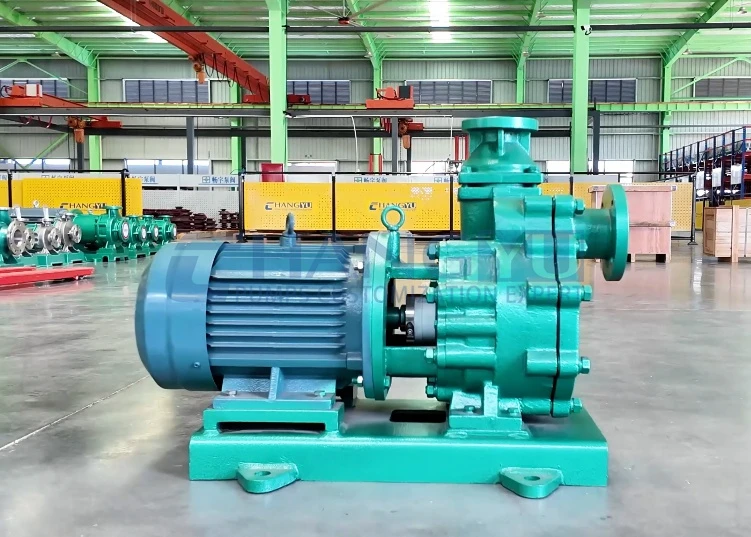
Kavitasi adalah salah satu masalah yang paling umum dan merusak pada pompa sentrifugal. Memahami apa yang menyebabkannya — dan bagaimana mencegahnya — dapat menghemat ribuan biaya perbaikan dan waktu henti yang tidak terencana.
Seperti Apa Suara dan Rasa Kavitasi
Bayangkan memanaskan panci berisi air di atas kompor. Saat air mendekati titik didih, gelembung terbentuk di dasar dan naik ke permukaan. Sekarang bayangkan gelembung-gelembung itu meledak dengan hebat — bukan di permukaan, tetapi di permukaan logam impeller. Setiap gelembung yang meledak menciptakan semburan air mikroskopis yang menghantam impeller dengan kekuatan yang cukup untuk mengikis logam seiring waktu.
Inilah kavitasi: pembentukan dan ledakan hebat gelembung uap di dalam pompa. Ini memiliki suara yang khas — seperti kerikil atau kelereng yang berderak di dalam rumah pompa. Jika Anda mendengar suara ini, pompa Anda mengalami kavitasi dan membutuhkan perhatian segera. Jika dibiarkan, kavitasi akan membuat lubang dan mengikis impeller, meningkatkan getaran, mengurangi aliran, dan pada akhirnya merusak pompa.
Mengapa Kavitasi Terjadi
Kavitasi terjadi ketika tekanan pada hisapan pompa turun di bawah tekanan uap fluida. Ketika ini terjadi, cairan benar-benar mendidih pada suhu kamar — membentuk gelembung uap. Saat gelembung-gelembung ini bergerak melalui impeller ke area dengan tekanan lebih tinggi, mereka meledak dengan hebat, menciptakan suara dan kerusakan yang khas.
Penyebab paling umum kavitasi:
- Tekanan hisap tidak mencukupi: Level fluida di tangki suplai terlalu rendah, atau pipa hisap terlalu panjang atau terlalu sempit.
- Saringan hisap tersumbat: Saringan yang tersumbat membatasi aliran ke pompa, mengurangi tekanan hisap.
- Beroperasi pada aliran berlebihan: Seiring meningkatnya aliran, pompa membutuhkan lebih banyak tekanan hisap. Menjalankan pompa melebihi aliran desainnya dapat mendorong NPSHr di atas NPSHa.
- Suhu fluida tinggi: Fluida yang lebih hangat memiliki tekanan uap yang lebih tinggi dan membutuhkan tekanan hisap yang lebih besar untuk mencegah pendidihan.
NPSH: Ukuran Teknis Risiko Kavitasi
NPSH (Net Positive Suction Head) adalah parameter teknis yang digunakan untuk menilai risiko kavitasi:
- NPSHr (dibutuhkan): Tekanan hisap minimum yang dibutuhkan pompa pada laju aliran tertentu. Ini adalah karakteristik pompa — berasal dari pabrikan pompa.
- NPSHa (tersedia): Tekanan hisap aktual yang disediakan sistem pada saluran masuk pompa. Ini adalah karakteristik sistem — bergantung pada level tangki, ukuran pipa, suhu fluida, dan tekanan atmosfer.
Aturan fundamental: NPSHa harus melebihi NPSHr dengan margin keselamatan — setidaknya 1 meter atau 30% dari NPSHr, mana yang lebih besar — untuk pengoperasian pompa yang andal. Jika NPSHa turun di bawah NPSHr, kavitasi dimulai.
Tiga Cara Mencegah Kavitasi
- Kurangi gesekan pipa hisap: Gunakan pipa hisap berdiameter lebih besar dan minimalkan belokan serta fitting. Setiap fitting menambah kehilangan tekanan yang mengurangi NPSHa.
- Jaga saringan hisap tetap bersih: Saringan yang tersumbat adalah salah satu penyebab kavitasi yang paling umum. Periksa dan bersihkan saringan setiap minggu.
- Pilih pompa dengan NPSHr yang lebih rendah: Jika sistem tidak dapat menyediakan tekanan hisap yang memadai, pilih pompa yang dirancang untuk layanan NPSH rendah. Impeller hisap ganda dan mata impeller yang lebih besar mengurangi NPSHr.
Langkah 5: Pilih Spesifikasi Motor. Jika Anda mendengar kavitasi — suara khas seperti kerikil — segera kurangi aliran pompa dengan menutup katup buang hingga suara berhenti. Ini adalah tindakan sementara yang melindungi pompa sementara Anda mendiagnosis dan memperbaiki akar penyebabnya. Minimalkan pengoperasian pompa yang mengalami kavitasi — matikan sesegera mungkin dengan aman untuk mencegah kerusakan impeller.
Kapan Pompa Sentrifugal Menjadi Pilihan yang Tepat?
Pompa sentrifugal menangani mayoritas aplikasi transfer fluida industri, tetapi tidak selalu menjadi pilihan yang tepat untuk setiap fluida. Memahami aplikasi pompa sentrifugal dan batasannya membantu menghindari kesalahan spesifikasi yang mahal.
Pompa Sentrifugal vs Pompa Perpindahan Positif
Pompa sentrifugal dan pompa perpindahan positif memindahkan fluida menggunakan mekanisme yang fundamental berbeda. Pompa sentrifugal menambahkan kecepatan dan mengubahnya menjadi tekanan; pompa perpindahan positif menjebak volume fluida tetap dan mendorongnya secara mekanis. Perbedaan ini menentukan jenis pompa mana yang cocok untuk aplikasi mana.
Tabel: Pompa Sentrifugal vs Pompa Perpindahan Positif
| Faktor Aplikasi | Pompa Sentrifugal | Pompa Perpindahan Positif |
|---|---|---|
| Rentang viskositas terbaik | Di bawah 200–300 cSt | Di atas 200 cSt; menangani hingga 1.000.000+ cSt |
| Hubungan antara debit dan tekanan | Aliran menurun saat tekanan meningkat | Aliran tetap hampir konstan terlepas dari tekanan |
| Penanganan bahan padat | Buruk — impeller tertutup tersumbat; impeller semi-terbuka mentolerir padatan terbatas | Sangat baik — pompa progressive cavity dan diafragma menangani padatan, serat, dan abrasif |
| Sensitivitas geser | Tinggi — impeller dapat merusak fluida yang sensitif terhadap geseran | Rendah — aksi pemompaan yang lembut dan berkecepatan rendah |
| Pulsasi aliran | Aliran halus dan kontinu | Aliran berdenyut (dapat diredam) |
| Pemancing otomatis | Tidak — desain standar memerlukan hisap terendam (pompa sentrifugal self-priming tersedia untuk aplikasi tertentu) | Beberapa jenis (diafragma, peristaltik); bukan progressive cavity atau gear pump |
Kapan Memilih Pompa Sentrifugal
- Fluida encer dan bersih (viskositas di bawah 200 cSt)
- Laju aliran tinggi diperlukan (pompa sentrifugal menangani hingga ribuan m³/jam)
- Aliran yang stabil dan kontinu diperlukan
- Aplikasi tidak memerlukan metering presisi
- Pompa dapat dipasang dengan hisap terendam atau NPSH yang memadai
Kapan Mempertimbangkan Alternatif
- Viskositas fluida melebihi 200–300 cSt — efisiensi pompa sentrifugal turun dengan cepat
- Fluida mengandung padatan abrasif — erosi impeller dan kegagalan seal
- Metering atau dosing presisi diperlukan — gunakan pompa perpindahan positif
- Pompa harus self-priming dari atas sumber fluida — gunakan pompa diafragma
FAQ tentang Cara Kerja Pompa Sentrifugal
T: Bagaimana pompa sentrifugal menciptakan tekanan?
J: Impeller mempercepat fluida ke arah luar dengan gaya sentrifugal, meningkatkan kecepatannya. Rumah volute melebar secara bertahap, mengubah kecepatan ini menjadi tekanan. Pompa tidak menciptakan tekanan secara langsung — pompa menciptakan aliran, dan tekanan berkembang ketika aliran tersebut ditahan oleh sistem.
T: Apa bagian terpenting dari pompa sentrifugal?
J: Impeller adalah komponen kerja utama yang mentransfer energi dari motor ke fluida. Desain impeller menentukan laju aliran pompa, kemampuan head, dan efisiensi. Mechanical seal, meskipun sering menjadi bagian yang paling intensif perawatan, sama pentingnya untuk pengoperasian yang andal.
T: Dapatkah pompa sentrifugal beroperasi kering?
J: Tidak — fluida yang dipompa melumasi dan mendinginkan mechanical seal. Beroperasi kering merusak seal dalam hitungan menit. Tidak seperti pompa diafragma yang mentolerir operasi kering, pompa sentrifugal tidak boleh beroperasi tanpa fluida di dalam casing.
T: Mengapa pompa sentrifugal saya berisik?
J: Penyebab paling umum kebisingan pompa adalah kavitasi (suara berderak seperti kerikil), kegagalan bantalan (suara gerinda atau mencicit), atau ketidaksejajaran (getaran dan dengung). Kavitasi memerlukan perhatian segera — kurangi aliran dan selidiki kondisi hisap.
T: Bagaimana saya tahu jika pompa sentrifugal saya beroperasi secara efisien?
J: Periksa apakah pompa beroperasi dalam 80–110% dari Best Efficiency Point (BEP). Flow meter, pengukur tekanan, dan monitor daya menyediakan data yang diperlukan untuk menghitung efisiensi operasi aktual. Pompa yang beroperasi jauh dari BEP membuang energi dan mempercepat keausan.
Ingin Tahu Lebih Lanjut? Jelajahi Solusi Pompa Sentrifugal Changyu Pump
Sekarang Anda memahami cara kerja pompa sentrifugal, memilih yang tepat untuk aplikasi Anda adalah langkah berikutnya. Tim teknik Changyu Pump dapat membantu Anda mencocokkan spesifikasi pompa — material, desain impeller, konfigurasi seal — dengan kebutuhan proses spesifik Anda. Dua dekade pengalaman manufaktur pompa di seluruh pemrosesan kimia, pengolahan air, dan aplikasi industri mendasari setiap rekomendasi.
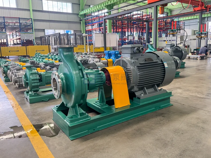
Jelajahi rangkaian produk pompa sentrifugal kami atau hubungi tim teknik kami untuk penilaian teknis gratis.