
Quick Answer
A centrifugal pump moves fluid by converting rotational kinetic energy from an impeller into fluid velocity, then into pressure at the volute. At its best efficiency point (BEP), a properly sized industrial centrifugal pump converts 75–90% of motor input power into fluid power — smaller pumps (under 5 kW) typically achieve 50–70%. Operating away from BEP can waste significant energy annually. The process follows four steps: fluid enters the impeller eye, the rotating impeller flings fluid outward by centrifugal force, the fluid gains velocity and pressure, and the volute converts the remaining velocity into usable discharge pressure.
Centrifugal pumps are the most widely used pump type in industrial fluid handling, moving everything from clean water to corrosive chemicals. Whether in municipal water supply, HVAC systems, chemical processing, or desalination plants, the same fundamental principle applies: a spinning impeller creates the force that moves fluid through the system.
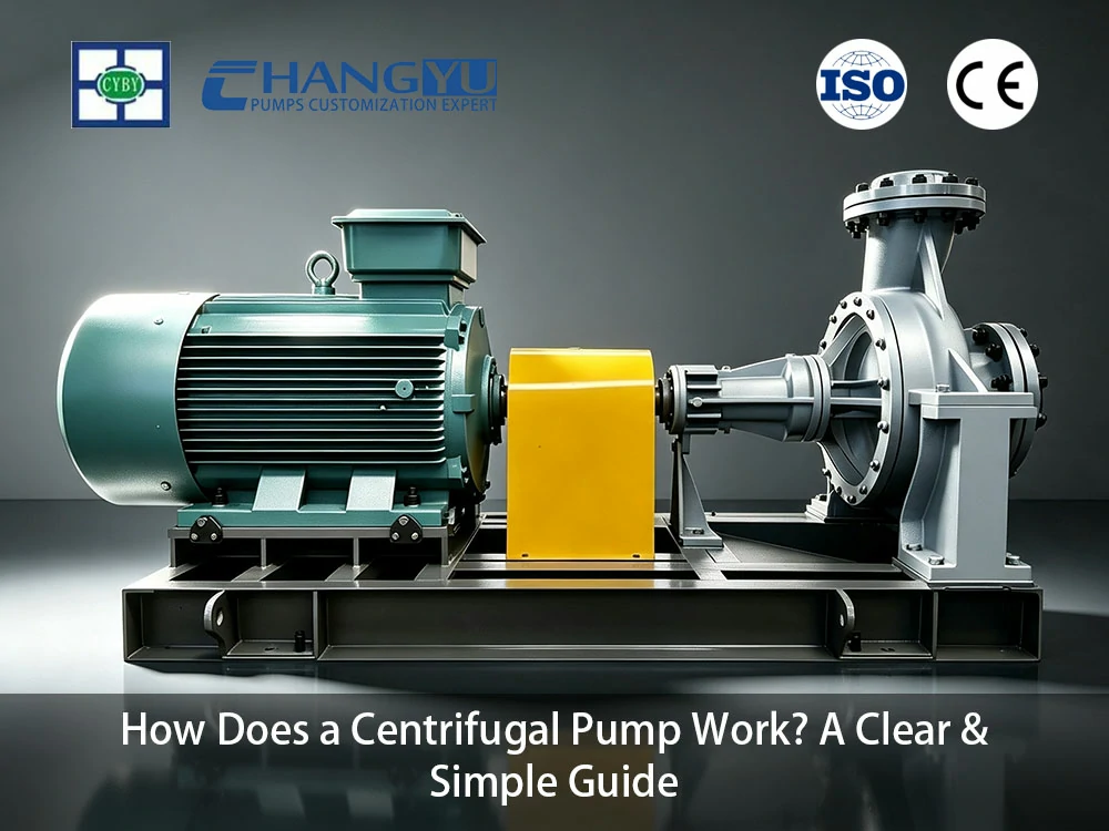
This guide explains how centrifugal pumps work — from the basic principle and key components to performance curves and cavitation — in clear, practical terms. No prior pump knowledge is required.
Centrifugal Pump Key Terms at a Glance
Table: Centrifugal Pump Key Terms at a Glance
| Term | Definition |
|---|---|
| Impeller | The rotating component with curved vanes that transfers energy to the fluid |
| Volute | The spiral casing that collects fluid from the impeller and converts velocity into pressure |
| BEP (Best Efficiency Point) | The flow rate at which the pump operates at maximum hydraulic efficiency |
| Cavitation | Formation and collapse of vapor bubbles in the pump, causing noise, vibration, and impeller damage |
| NPSH (Net Positive Suction Head) | The pressure margin required at the pump suction to prevent cavitation |
| Head | The height to which the pump can lift fluid, expressed in meters or feet of liquid column |
| Mechanical Seal | The sealing component that prevents fluid leakage along the rotating shaft |
1. How Does a Centrifugal Pump Work? The Simple Principle
The centrifugal pump working principle can be understood in four steps, each corresponding to what happens to the fluid as it passes through the pump.
Step 1: Fluid Enters the Impeller Eye
Fluid enters the pump through the suction nozzle and flows into the center of the impeller — called the impeller eye. The impeller is a rotating disk with curved vanes, mounted on a shaft driven by an electric motor or engine. At this point, the fluid has relatively low velocity and low pressure — it is simply being drawn in by the rotation of the impeller.
Step 2: The Impeller Accelerates the Fluid
As the impeller spins (typically at 1,450–3,600 r/min), the curved vanes catch the fluid and fling it outward by centrifugal force. This is the same force you feel when you swing a bucket of water in a circle — the water is pushed outward against the bucket wall. Inside the pump, the impeller vanes accelerate the fluid from the center to the outer edge, dramatically increasing its velocity.
At the impeller exit, the fluid has gained significant kinetic energy (velocity) and some pressure. This conversion of mechanical shaft power into fluid energy is the core function of the impeller.
Step 3: The Volute Converts Velocity into Pressure
The fluid leaving the impeller enters the volute — a spiral-shaped casing that surrounds the impeller. The volute passage gradually widens as it wraps around the impeller. This widening passage acts like a highway exit ramp: as the lane widens, traffic slows down but becomes denser. Similarly, as the volute cross-section increases, fluid velocity decreases and the kinetic energy converts into pressure energy.
This conversion is essential because most industrial applications need pressure (to overcome pipe friction, lift fluid to height, or force it through filters) rather than raw velocity.
Step 4: Fluid Is Discharged
At the end of the volute, the fluid reaches the discharge nozzle at the pump’s rated pressure and flow rate. The fluid has now completed its journey through the pump — entering at low pressure and velocity, and leaving at high pressure with controlled flow. This continuous process repeats as long as the impeller rotates and fluid is supplied to the suction.
In short: the impeller adds velocity; the volute converts velocity into pressure. This two-stage energy conversion is what defines a centrifugal pump.
2. What Are the Key Parts of a Centrifugal Pump?
A centrifugal pump consists of relatively few components, but each plays a specific role in moving and controlling the fluid. Understanding these parts makes pump selection and troubleshooting far more intuitive.
The Five Essential Components
Impeller:
The impeller is the primary working component of the centrifugal pump. It is a rotating disk with curved vanes that transfer mechanical energy from the motor shaft to
the fluid. Impellers come in several designs: closed (with front and back shrouds for maximum efficiency with clean fluids), semi-open (with a back shroud only, for fluids with some solids), and open (no shrouds, for viscous or solids-laden fluids). The impeller diameter and vane geometry determine the pump’s flow rate and head capability.
Volute (Casing):
The volute is the stationary housing that surrounds the impeller. Its spiral shape is critical — the gradually increasing cross-sectional area converts the high-velocity fluid leaving the impeller into usable pressure at the discharge. The volute also collects fluid from the impeller and directs it to the discharge nozzle. In some pump designs, a diffuser (a ring of stationary vanes) is used instead of or in addition to a volute for more controlled pressure recovery.
Shaft and Bearings:
The shaft connects the impeller to the motor and transmits rotational power. It must be precisely machined and aligned to minimize vibration. Bearings support the shaft, allowing it to rotate freely while absorbing radial and axial loads from the impeller. Oversized, heavy-duty bearings are specified for continuous-duty industrial pumps.
Mechanical Seal:
The mechanical seal is the critical component that prevents fluid from leaking along the rotating shaft where it exits the pump casing. It consists of two flat faces — one rotating with the shaft, one stationary in the casing — pressed together by a spring. A microscopic fluid film between the faces provides lubrication and cooling. Standard mechanical seals handle clean, non-crystallizing fluids; double seals or seal flush systems are required for abrasive, corrosive, or crystallizing fluids. For demanding applications, external seal flush systems provide cooling and prevent solids from reaching the seal faces.
Suction and Discharge Nozzles:
The suction nozzle connects to the incoming pipe and delivers fluid to the impeller eye. The discharge nozzle connects to the outgoing pipe at the volute exit. The size and orientation of these nozzles determine how the pump integrates into the piping system.
Key Components Summary
Table: Centrifugal Pump Key Components
| Component | Function | Common Materials |
|---|---|---|
| Impeller | Transfers mechanical energy to fluid | Cast iron, 316L SS, Duplex 2205, High-chrome alloy |
| Volute / Casing | Converts velocity into pressure | Cast iron, ductile iron, 316L SS, FEP/PFA-lined |
| Shaft | Transmits motor power to impeller | High-strength alloy steel, 316L SS |
| Bearings | Support shaft rotation; absorb loads | Grease-lubricated ball or roller bearings |
| Mechanical Seal | Prevents leakage along shaft | Carbon vs. ceramic or tungsten carbide faces; EPDM, FKM, or PTFE O-rings |
3. How to Read a Centrifugal Pump Performance Curve and Avoid Costly Mistakes
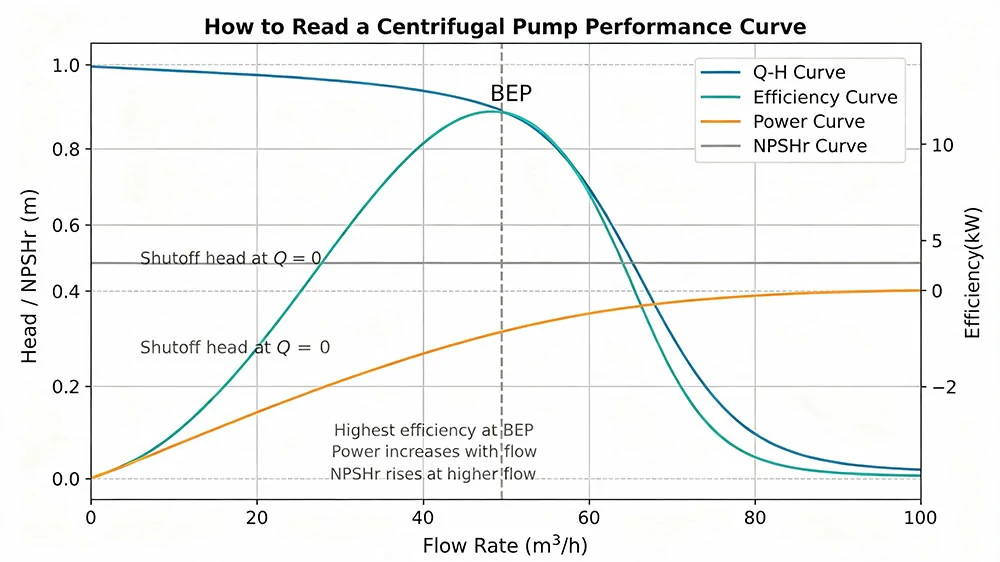
A centrifugal pump performance curve is a graph that shows how the pump behaves at different flow rates. Learning to read this curve is essential for selecting the right pump and avoiding costly operating errors.
The Four Curves on a Pump Performance Chart
Flow-Head Curve (Q-H Curve):
This is the most important curve. It shows how much head (pressure) the pump produces at different flow rates. As flow increases, head decreases — the pump produces maximum head at zero flow (shutoff) and minimum head at maximum flow. The shape of this curve determines whether the pump maintains stable flow as system conditions change. A steep curve (large head change for small flow change) provides stable flow control; a flat curve maintains near-constant head across a wide flow range.
Efficiency Curve:
This curve shows the pump’s hydraulic efficiency at different flow rates. Efficiency peaks at the Best Efficiency Point (BEP) — the flow rate where the pump operates most cost-effectively. Operating away from BEP, particularly below 50% or above 120% of BEP flow, wastes energy, increases vibration, and accelerates bearing and seal wear. A pump sized correctly for its application should operate within 80–110% of BEP.
Power Curve:
This curve shows the motor power consumed at different flow rates. For most centrifugal pumps, power consumption increases with flow — the pump draws more power as it moves more fluid. This is important for motor sizing: the motor must be rated for the maximum power the pump will draw across its entire operating range.
NPSHr Curve (Net Positive Suction Head Required):
This curve shows the minimum suction pressure the pump needs at each flow rate to avoid cavitation. NPSHr increases with flow — the pump demands more suction pressure as flow increases. The actual suction pressure available in the system (NPSHa) must exceed NPSHr by a safety margin for the pump to operate without cavitation.
In short: the head curve tells you how high the pump can lift; the efficiency curve tells you where it costs the least to operate; the power curve tells you how large your motor must be; and the NPSHr curve tells you how much suction pressure you need.
Engineers at Changyu Pump note: Operating within 80–110% of BEP is one of the most important specification decisions for pump longevity and energy efficiency. Pumps operating below 50% of BEP experience high radial loads that accelerate bearing wear; pumps above 120% of BEP risk cavitation and motor overload. Both extremes waste energy and shorten pump life. Equally important is material compatibility — a pump operating at BEP will still fail rapidly if its materials are incompatible with the process fluid.
4. What Is Centrifugal Pump Cavitation and How to Prevent It?
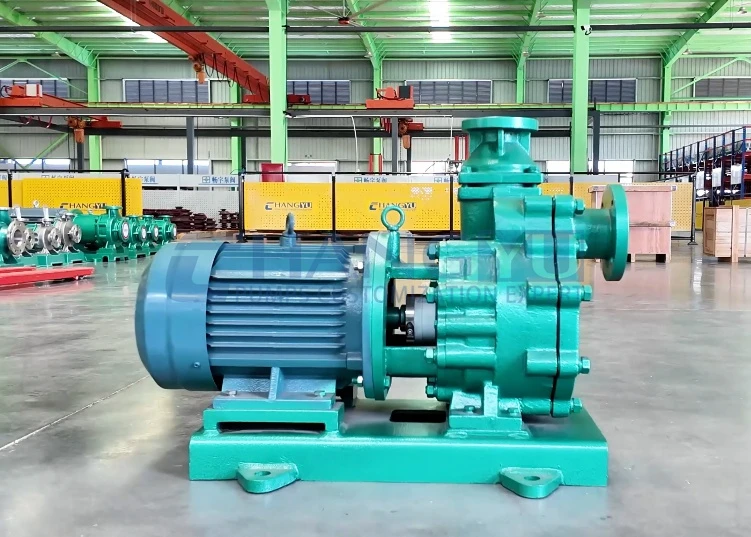
Cavitation is one of the most common and destructive problems in centrifugal pumps. Understanding what causes it — and how to prevent it — can save thousands in repair costs and unplanned downtime.
What Cavitation Sounds and Feels Like
Imagine heating a pot of water on a stove. As the water approaches boiling, bubbles form at the bottom and rise to the surface. Now imagine those bubbles collapsing violently — not at the surface, but against the metal surface of the impeller. Each collapsing bubble creates a microscopic jet of water that strikes the impeller with enough force to erode metal over time.
This is cavitation: the formation and violent collapse of vapor bubbles in the pump. It has a distinctive sound — like gravel or marbles rattling inside the pump casing. If you hear this sound, your pump is cavitating and needs immediate attention. Left unchecked, cavitation will pit and erode the impeller, increase vibration, reduce flow, and ultimately destroy the pump.
Why Cavitation Happens
Cavitation occurs when the pressure at the pump suction drops below the fluid’s vapor pressure. When this happens, the liquid literally boils at room temperature — forming vapor bubbles. As these bubbles travel through the impeller to areas of higher pressure, they collapse violently, creating the characteristic noise and damage.
The most common causes of cavitation:
- Insufficient suction pressure: The fluid level in the supply tank is too low, or the suction pipe is too long or too narrow.
- Clogged suction strainer: A blocked strainer restricts flow into the pump, reducing suction pressure.
- Operating at excessive flow: As flow increases, the pump demands more suction pressure. Running the pump beyond its design flow can push NPSHr above NPSHa.
- High fluid temperature: Warmer fluids have higher vapor pressure and require more suction pressure to prevent boiling.
NPSH: The Technical Measure of Cavitation Risk
NPSH (Net Positive Suction Head) is the technical parameter used to assess cavitation risk:
- NPSHr (required): The minimum suction pressure the pump needs at a given flow rate. This is a pump characteristic — it comes from the pump manufacturer.
- NPSHa (available): The actual suction pressure the system provides at the pump inlet. This is a system characteristic — it depends on tank level, pipe size, fluid temperature, and atmospheric pressure.
The fundamental rule: NPSHa must exceed NPSHr by a safety margin — at least 1 meter or 30% of NPSHr, whichever is larger — for reliable pump operation. If NPSHa drops below NPSHr, cavitation begins.
Three Ways to Prevent Cavitation
- Reduce suction pipe friction: Use larger-diameter suction pipes and minimize bends and fittings. Every fitting adds pressure loss that reduces NPSHa.
- Keep suction strainers clean: A clogged strainer is one of the most common causes of cavitation. Inspect and clean strainers weekly.
- Select a pump with lower NPSHr: If the system cannot provide adequate suction pressure, select a pump designed for low-NPSH service. Double-suction impellers and larger impeller eyes reduce NPSHr.
Engineers at Changyu Pump recommend: If you hear cavitation — that characteristic gravel-like sound — reduce pump flow immediately by throttling the discharge valve until the noise stops. This is a temporary measure that protects the pump while you diagnose and fix the root cause. Minimize operation of a cavitating pump — shut it down as soon as safely possible to prevent impeller damage.
5. When Is a Centrifugal Pump the Right Choice?
Centrifugal pumps handle the majority of industrial fluid transfer applications, but they are not the right choice for every fluid. Understanding centrifugal pump applications and their boundaries helps avoid costly specification errors.
Centrifugal Pump vs Positive Displacement Pump
Centrifugal pumps and positive displacement pumps move fluid using fundamentally different mechanisms. Centrifugal pumps add velocity and convert it to pressure; positive displacement pumps trap a fixed volume of fluid and push it mechanically. This difference determines which pump type suits which application.
Table: Centrifugal Pump vs Positive Displacement Pump
| Application Factor | Centrifugal Pump | Positive Displacement Pump |
|---|---|---|
| Best viscosity range | Below 200–300 cSt | Above 200 cSt; handles up to 1,000,000+ cSt |
| Flow vs pressure relationship | Flow decreases as pressure increases | Flow remains nearly constant regardless of pressure |
| Solids handling | Poor — enclosed impellers clog; semi-open impellers tolerate limited solids | Excellent — progressive cavity and diaphragm pumps handle solids, fibers, and abrasives |
| Shear sensitivity | High — impeller can damage shear-sensitive fluids | Low — gentle, low-velocity pumping action |
| Flow pulsation | Smooth, continuous flow | Pulsating flow (can be dampened) |
| Self-priming | No — standard designs require flooded suction (self-priming centrifugal pumps are available for specific applications) | Some types (diaphragm, peristaltic); not progressive cavity or gear pumps |
When to Choose a Centrifugal Pump
- Fluid is thin and clean (viscosity below 200 cSt)
- High flow rates are required (centrifugal pumps handle up to thousands of m³/h)
- Steady, continuous flow is needed
- The application does not require precise metering
- The pump can be installed with a flooded suction or adequate NPSH
When to Consider an Alternative
- Fluid viscosity exceeds 200–300 cSt — centrifugal pump efficiency drops rapidly
- Fluid contains abrasive solids — impeller erosion and seal failure
- Precise metering or dosing is required — use a positive displacement pump
- The pump must self-prime from above the fluid source — use a diaphragm pump
FAQs about How Centrifugal Pumps Work
Q: How does a centrifugal pump create pressure?
A: The impeller accelerates fluid outward by centrifugal force, increasing its velocity. The volute casing gradually widens, converting this velocity into pressure. The pump does not create pressure directly — it creates flow, and pressure develops when that flow is resisted by the system.
Q: What is the most important part of a centrifugal pump?
A: The impeller is the primary working component that transfers energy from the motor to the fluid. Impeller design determines the pump’s flow rate, head capability, and efficiency. The mechanical seal, while often the most maintenance-intensive part, is equally critical for reliable operation.
Q: Can a centrifugal pump run dry?
A: No — the pumped fluid lubricates and cools the mechanical seal. Running dry destroys the seal within minutes. Unlike diaphragm pumps, which tolerate dry running, centrifugal pumps must never operate without fluid in the casing.
Q: Why is my centrifugal pump noisy?
A: The most common causes of pump noise are cavitation (a gravel-like rattling sound), bearing failure (a grinding or squealing sound), or misalignment (vibration and humming). Cavitation requires immediate attention — reduce flow and investigate suction conditions.
Q: How do I know if my centrifugal pump is operating efficiently?
A: Check whether the pump operates within 80–110% of its Best Efficiency Point (BEP). Flow meters, pressure gauges, and power monitors provide the data needed to calculate actual operating efficiency. A pump operating far from BEP wastes energy and accelerates wear.
Want to Learn More? Explore Changyu Pump’s Centrifugal Pump Solutions
Now that you understand how a centrifugal pump works, selecting the right one for your application is the next step. Changyu Pump’s engineering team can help you match pump specifications — materials, impeller design, seal configuration — to your specific process requirements. Two decades of pump manufacturing experience across chemical processing, water treatment, and industrial applications inform every recommendation.
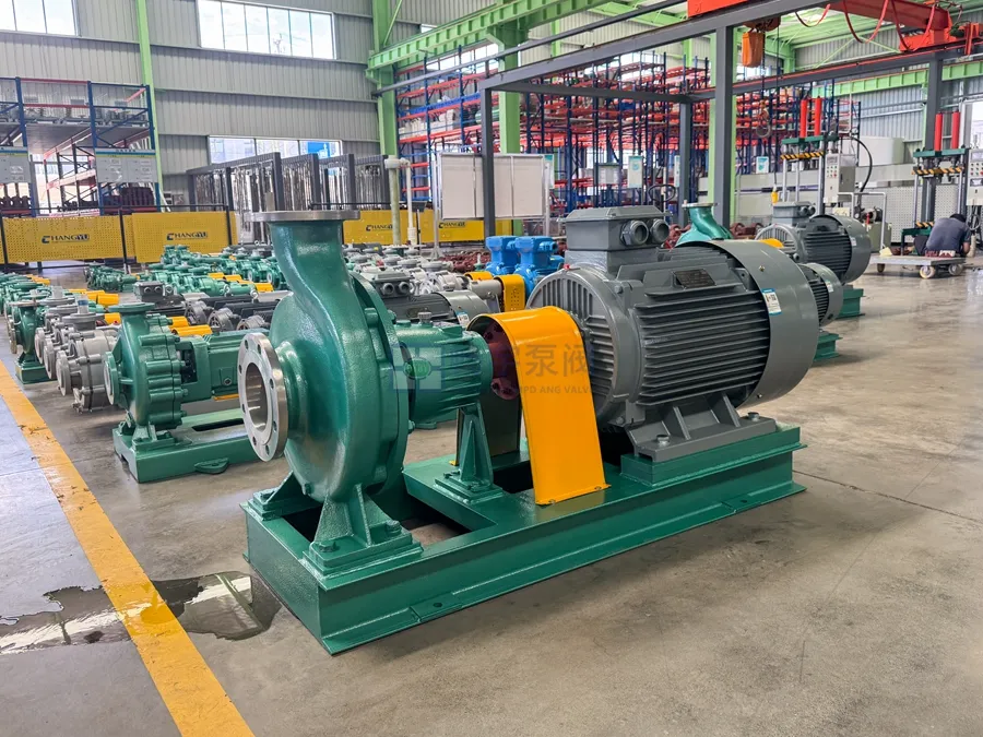
Explore our centrifugal pump product range or contact our engineering team for a free technical assessment.