
Resposta rápida
Selecionar o caminho certo bomba de lama para fluxo de retorno de fraturamento requer a correspondência de materiais para abrasão extrema causada pela areia de fraturamento, escolha de projetos de rotor que resistam a entupimentos e lidem com gás arrastado, e especificação de selos que suportem lamas abrasivas em condições remotas de campos petrolíferos. A areia de fraturamento (Mohs 7, tamanho de partícula de até 840 μm) em altas velocidades de fluxo pode desgastar rotores padrão de liga de alto cromo em 3–4 semanas. Revestimentos cerâmicos estendem a vida útil para 6–12 meses sob as mesmas condições. Quatro fatores principais de seleção:
- Resistência do material à abrasão severa: O fluido de fluxo de retorno carrega altas concentrações de areia de sílica e recortes de formação angulares. A taxa de desgaste abrasivo é proporcional ao cubo da velocidade do fluxo — dobrar a vazão aumenta o desgaste aproximadamente 8×. A liga de alto cromo Cr33/Cr33M fornece a linha de base para condições moderadas; carboneto de tungstênio e revestimentos cerâmicos oferecem vida útil significativamente maior em serviços de alta velocidade e alta areia.
- Projeto do rotor para sólidos e gás: O fluido de fluxo de retorno frequentemente contém gás natural arrastado que pode causar bloqueio de vapor. Rotores vortex fornecem máxima resistência a entupimentos para sólidos imprevisíveis e manuseio parcial de gás; rotores semi-abertos equilibram a passagem de sólidos com maior eficiência.
- Integridade do selo em serviço abrasivo: Partículas de areia destroem selos padrão mecânicos em dias. Selos mecânicos duplos com lavagem externa API Plan 32 fornecem vedação confiável onde água limpa está disponível. Para plataformas de poços remotas sem água de lavagem confiável, selos centrífugos expelidores eliminam completamente a dependência de água externa.
- Adaptação à operação intermitente em campos petrolíferos: Bombas de fluxo de retorno de fraturamento operam em horários irregulares — serviço contínuo durante o pico de fluxo de retorno, depois inativas por semanas. Lavagem com água limpa antes do desligamento e rotação do eixo semanalmente durante períodos de inatividade previnem corrosão e aderência das faces do selo.
O fluxo de retorno de fraturamento é uma das aplicações de bombeamento mais punitivas na indústria de petróleo e gás. O fluido carrega altas concentrações de areia de sílica ou propante cerâmico — o mesmo material usado para fraturar formações de xisto — agora retornando à superfície em alta velocidade. Cada grão de areia que passa pela bomba atua como uma ferramenta de corte, erodindo rotores, carcaças e selos. Adicionando ao desafio, recortes de formação angulares e resíduos de lama de perfuração criam um efeito de desgaste composto mais severo do que apenas o propante arredondado. Uma bomba de lama padrão pode exigir substituição do conjunto úmido em semanas, enquanto uma bomba com materiais especificados incorretamente pode falhar em dias.
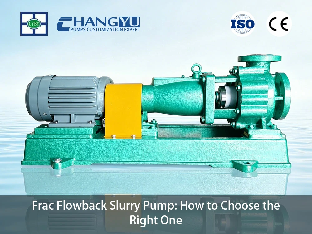
A Changyu Pump fabrica bombas resistentes ao desgaste para aplicações em mineração, química e campos petrolíferos há mais de duas décadas. Este guia cobre a seleção de materiais, projeto do rotor, proteção do selo e práticas operacionais que determinam se uma bomba de lama para fluxo de retorno de fraturamento sobrevive à temporada de fraturamento ou se torna uma despesa recorrente de substituição.
O Que É uma Bomba de Lama para Fluxo de Retorno de Fraturamento e Por Que Ela É Diferente?
Uma bomba de lama para fluxo de retorno de fraturamento lida com o fluido que retorna à superfície após o fraturamento hidráulico. Este fluido de fluxo de retorno é uma mistura de fluido de fraturamento injetado, água de formação, propante (partículas de areia ou cerâmica), recortes de formação angulares, resíduos de lama de perfuração e aditivos químicos. A bomba deve operar sob altas vazões, condições de pressão variável e — em muitos casos — locais remotos de poços com acesso limitado para manutenção.
Características Principais do Fluido de Fluxo de Retorno de Fraturamento
- Alta concentração de sólidos: A carga de propante pode variar de traços a mais de 10% em volume durante os picos de retorno de areia. Os tamanhos de partícula variam de finos (100 mesh, ~150 μm) a grossos (20/40 mesh, ~420–840 μm).
- Dureza das partículas abrasivas: A areia de fraturamento é principalmente quartzo (Mohs 7, aproximadamente 800–1.000 HV). Propantes cerâmicos podem atingir Mohs 9.
- Desgaste composto por sólidos mistos: Além da areia de fraturamento esférica, o fluido de fluxo de retorno frequentemente contém recortes de formação angulares e resíduos de lama de perfuração. Essas partículas irregulares causam desgaste de corte mais severo do que o propante arredondado da mesma dureza, pois suas bordas afiadas concentram força em áreas de contato menores.
- Condições de fluxo variável: As taxas de fluxo de retorno diminuem ao longo do tempo à medida que a pressão da formação se esgota. As bombas devem operar eficientemente em uma ampla faixa de vazão.
- Gás arrastado: Gás natural, dióxido de carbono e sulfeto de hidrogênio podem estar presentes no fluido de fluxo de retorno, causando bloqueio de vapor em bombas não projetadas para manuseio de gás.
- Operação intermitente: O fluxo de retorno é inerentemente não contínuo — as bombas podem funcionar 24/7 por dias, depois ficar inativas por semanas entre os estágios de fraturamento.
Principais Diferenças em Relação às Bombas de Lama Padrão
Tabela: Bomba de Lama para Fluxo de Retorno de Fraturamento vs Bomba de Lama Padrão
| Caraterística | Bomba de polpa padrão | Bomba de Lama para Fluxo de Retorno de Fraturamento |
|---|---|---|
| Materiais húmidos | Direciona o fluxo da polpa; absorve o desgaste dos sólidos | Alto cromo Cr33/Cr33M, carboneto de tungstênio ou revestimentos cerâmicos |
| Impulsor | Fechado ou semi-aberto | Vortex ou semi-aberto com tratamento resistente ao desgaste |
| Selo | Mecânico simples | Mecânico duplo com lavagem API Plan 32 ou expelidor centrífugo |
| Manuseio de gás | Nenhum | Manuseio parcial de gás via rotor aberto ou projeto vortex |
| Conjunto de rolamentos | Padrão | Superdimensionado para operação contínua de alta carga |
| Padrão operacional | Funcionamento contínuo | Intermitente — projetado para partidas/paradas frequentes e períodos de inatividade |
Quais Materiais Resistem à Abrasão em Bombas de Lama para Fluxo de Retorno de Fraturamento?
A seleção de materiais é a decisão mais crítica para uma bomba de lama para fluxo de retorno de fraturamento. A combinação de partículas de areia em alta velocidade, recortes de formação angulares e aditivos químicos cria um ambiente de desgaste extremo que materiais de bomba padrão não suportam.
Como o Fluxo de Retorno de Fraturamento Ataca os Materiais da Bomba
As partículas de areia de fraturamento são angulares e duras (Mohs 7). Quando essas partículas impactam as superfícies da bomba em alta velocidade — particularmente nas pontas das pás do rotor e no cutwater da voluta — elas cortam o material, removendo metal a cada contato.
O taxa de desgaste abrasivo A taxa de desgaste é proporcional ao cubo da velocidade do fluxo — dobrar a vazão aumenta o desgaste aproximadamente 8×. Isso explica por que bombas lidando com concentrações de areia aparentemente semelhantes podem experimentar vidas úteis dramaticamente diferentes dependendo da velocidade do fluxo na bomba.
Os fragmentos de formação angulares agravam esse efeito. Diferentemente das partículas de propante arredondadas que podem rolar sobre as superfícies da bomba, os fragmentos de bordas afiadas concentram a força de impacto em pequenas áreas de contato, escavando o material da superfície em vez de erodi-lo gradualmente.
Opções de Materiais para Serviço de Fluxo de Retorno de Fraturamento
Tabela: Seleção de Materiais para Bombas de Polpa de Fluxo de Retorno de Fraturamento
| Material | Vida Útil Típica no Fluxo de Retorno de Fraturamento | Melhor para | Limitações |
|---|---|---|---|
| High-Chrome Cr27 (650–700 HB) | 3–6 semanas (alta velocidade); 8–12 semanas (baixa velocidade) | Baixo teor de areia, baixa velocidade, orçamento limitado | Desgaste rápido em areia de alta velocidade; corrói abaixo de pH 4 |
| High-Chrome Cr33/Cr33M (700–750 HB) | 6–12 semanas (alta velocidade); 12–20 semanas (baixa velocidade) | Teor moderado de areia e velocidade | Custo mais alto que o Cr27; ainda desgasta em condições extremas |
| Revestimentos de Carboneto de Tungstênio (HV 1200–1800) | 6–12 meses | Fluxo de retorno de alta velocidade e partículas finas; preferido para resistência ao impacto | Custo mais alto; pode fraturar sob impacto de fragmentos muito grandes |
| Revestimentos Cerâmicos — SiC (HV 2200–2800) | 6–12 meses (partículas finas, baixo impacto); 3–6 meses (partículas grossas com risco de impacto) | Areia fina de alta velocidade com impacto mínimo | Risco de fratura frágil por partículas acima de 2 mm ou fragmentos angulares |
| Compósito de Cerâmica e Borracha | 6–12 meses | Tamanhos mistos de partículas com risco de impacto | Custo mais alto; o suporte de borracha absorve a energia do impacto |
| Forro em UHMW-PE | 2–4 meses com fragmentos angulares; 3–6 meses apenas com areia arredondada | Baixa velocidade, teor moderado de areia com partículas arredondadas | Limite de temperatura de 90°C; não indicado para areia grossa de alta velocidade ou fragmentos angulares |
Correspondência de Materiais por Condições de Fluxo de Retorno
Tabela: Correspondência de Materiais por Condições de Fluxo de Retorno
| Condição de Fluxo de Retorno | Concentração de Areia | Velocidade de Fluxo | Material recomendado |
|---|---|---|---|
| Fluxo de retorno em estágio inicial (pico de areia) | Alta (> 5% em volume) | Alta (> 5 m/s) | Carboneto de tungstênio (preferido para resistência ao impacto) ou revestimentos cerâmicos (para fluxo de retorno de partículas finas e baixo impacto) |
| Fluxo de retorno em estágio intermediário (areia em declínio) | Moderada (2–5%) | Moderada (3–5 m/s) | High-Chrome Cr33/Cr33M |
| Fluxo de retorno em estágio final (areia residual) | Baixa (< 2%) | Baixa a moderada | High-Chrome Cr27 ou revestido com UHMW-PE |
| Fluxo de retorno com aditivos químicos | Variável | Variável | Duplex 2205 (resistente à corrosão) ou revestido com FEP/PFA |
Engenheiros da Changyu Pump observaram em instalações de bombas de fluxo de retorno de fraturamento: Para fluxo de retorno em estágio inicial com concentrações de pico de areia e altas velocidades, o High-Chrome Cr27 não é um material adequado — o desgaste do rotor em 3–4 semanas é comum. A atualização para High-Chrome Cr33/Cr33M proporciona melhoria incremental, mas a extensão de vida mais significativa vem de revestimentos de carboneto de tungstênio ou cerâmica, que podem estender a vida útil de semanas para meses. O prêmio de custo do material é tipicamente recuperado dentro dos dois primeiros estágios de fraturamento através da eliminação de trocas de bombas e redução do tempo não produtivo.
Por que o Projeto do Rotor é Importante para Bombas de Polpa de Fluxo de Retorno de Fraturamento?
O fluido de fluxo de retorno apresenta um duplo desafio para o projeto do rotor: sólidos abrasivos que obstruem passagens estreitas e gás arrastado que causa bloqueio de vapor. A seleção do rotor deve abordar ambos os modos de falha simultaneamente.
Tipos de Rotor para Serviço de Fluxo de Retorno
Quatro Tipos Comuns de Impulsores de Bomba de Esgoto
O rotor fica recuado na parede traseira da voluta, criando um vórtice que atrai fluido e sólidos através da bomba. Apenas uma fração do fluido entra em contato direto com o rotor, proporcionando a maior passagem livre para sólidos e quase imunidade a entupimentos. O projeto de vórtice também oferece capacidade parcial de manuseio de gás — bolhas de gás arrastado passam sem causar bloqueio de vapor. A eficiência é menor (35–55%), mas para fluxo de retorno em estágio inicial com sólidos e gás imprevisíveis, a confiabilidade supera a penalidade energética.
Impulsor semi-aberto:
As pás do rotor são fixadas a um disco traseiro sem um disco dianteiro. A face aberta permite que os sólidos passem sem as constrições dos projetos fechados. A eficiência é maior que a dos tipos de vórtice (50–60%). Adequado para fluxo de retorno em estágio intermediário a final, onde o teor de sólidos é menor e a fração de gás é reduzida. Rotores semiabertos podem ser fabricados com materiais resistentes ao desgaste ou revestimentos para vida útil prolongada.
Rotor de Canal:
Uma passagem larga simples ou dupla através do rotor acomoda sólidos. Maior eficiência (55–70%) do que projetos de vórtice ou semiabertos. Adequado para fluxo de retorno em estágio final ou transferência de água produzida, onde o teor de sólidos é baixo e previsível.
Estratégias de Manuseio de Gás para Bombas de Fluxo de Retorno
Quando o fluido de fluxo de retorno contém gás arrastado significativo, a bomba deve ser configurada para evitar o bloqueio de vapor — uma condição onde o gás se acumula no olho do rotor, bloqueando o fluxo de líquido.
- Instalação vertical da bomba: O gás sobe naturalmente para o topo da carcaça e sai pela descarga. Bombas verticais são inerentemente autoventilantes.
- Válvulas automáticas de liberação de ar: Instaladas no ponto alto da carcaça da bomba ou tubulação de descarga para ventilar o gás acumulado automaticamente.
- Rotores de vórtice ou abertos: Esses projetos permitem maior passagem de gás do que rotores fechados. Rotores de vórtice, em particular, lidam com até 20% de gás por volume sem perder a escorva.
Seleção de Rotor para Estágios de Fluxo de Retorno
Tabela: Seleção de Rotor para Estágios de Fluxo de Retorno
| Estágio de Fluxo de Retorno | Teor de sólidos | Fração de Gás | Matriz de Seleção de Impulsor de Bomba de Esgoto |
|---|---|---|---|
| Estágio inicial (pico de areia) | Alta, imprevisível | Elevado | Vórtice |
| Estágio intermediário (areia em declínio) | Moderado | Moderado | Semiaberto ou vortex |
| Estágio final (areia residual) | Baixa | Baixa | Semi-aberto ou canal |
| Transferência de água produzida | Muito baixo | Baixa | Canal |
Máxima passagem de sólidos + peças de desgaste substituíveis Para as primeiras 2–4 semanas de fluxo de retorno, quando o retorno de areia está no pico e o gás é mais prevalente, rotores de vórtice oferecem o menor risco de entupimento e bloqueio de vapor. À medida que o fluxo de retorno transita para condições de menor areia e gás, rotores semiabertos oferecem maior eficiência para o manuseio de água produzida a longo prazo. Considere manter uma bomba com rotor de vórtice dedicada ao fluxo de retorno em estágio inicial e uma bomba separada com rotor semiaberto para serviço contínuo de água produzida — o tempo de inatividade evitado de uma única bomba entupida justifica o custo do equipamento.

Como Prevenir Falha de Selo em Bombas de Polpa de Fluxo de Retorno de Fraturamento?
O vedação mecânica é o ponto de falha mais comum em bombas de fluxo de retorno de fraturamento. Partículas de areia que entram na câmara do selo atuam como um composto de retificação entre as faces do selo, destruindo-as em dias se nenhuma medida de proteção estiver em vigor.
Desafios de Vedação no Serviço de Fluxo de Retorno
- Ingresso de partículas abrasivas: Partículas finas de areia (malha 100 e mais finas) penetram na câmara de selagem, incrustando-se nas faces do selo e causando desgaste abrasivo rápido.
- Condições de pressão variável: A pressão de fluxo de retorno muda à medida que o poço se esgota, fazendo com que a carga nas faces do selo flutue.
- Operação intermitente: Durante períodos de inatividade, sólidos residuais na câmara de selagem podem se depositar e cimentar as faces do selo, causando danos na reinicialização.
- Limitações de locais remotos: Muitos locais de poços carecem de fornecimento confiável de água limpa para sistemas convencionais de lavagem de selo.
Soluções de Selagem para Bombas de Fluxo de Retorno de Fraturamento
Plano API 32 — Flushing Externo com Água Limpa:
Um fluxo contínuo de água limpa é injetado na câmara de selagem a uma pressão 1–2 bar acima da pressão da câmara de selagem. Isso cria uma barreira de fluido limpo nas faces do selo, impedindo que partículas de areia entrem em contato com o selo. A vazão é tipicamente de 4–12 L/min. Isso é confiável onde água de lavagem limpa está disponível, mas muitos locais remotos de poços carecem da infraestrutura de fornecimento de água e tratamento para suportá-lo.
Expelidor Centrífugo (Selo Dinâmico) com Enchimento de Gaxeta:
Quando água de lavagem limpa não está disponível — comum em locais remotos de poços — um expelidor centrífugo combinado com enchimento de gaxeta fornece selagem eficaz sem fornecimento externo de água. O expelidor é um pequeno impulsor aberto montado atrás do impulsor principal. Durante a operação da bomba, o expelidor cria um diferencial de pressão que empurra o fluido carregado de areia para longe da câmara de selagem. Durante a espera, o enchimento de gaxeta fornece o selo estático.
Este arranjo oferece uma vantagem crítica para aplicações de fluxo de retorno de fraturamento: elimina completamente a dependência de água de lavagem externa. Sem caminhões-pipa, sem sistemas de filtração, sem proteção contra congelamento — apenas a própria bomba mantendo a integridade do selo.
Plano API 53C — Selo Duplo com Fluido de Barreira Pressurizado:
Um selo mecânico duplo com um reservatório de fluido de barreira pressurizado. A pressão da barreira excede a pressão da câmara de selagem, impedindo que o fluido do processo atinja as faces do selo. Adequado para locais ambientalmente sensíveis onde qualquer vazamento do processo é inaceitável. Instale um manômetro e um alarme de baixa pressão no reservatório de fluido de barreira para fornecer aviso imediato de perda de fluido de barreira — uma perda de pressão da barreira significa que o selo interno está vazando e a bomba deve ser removida para substituição do selo antes que o selo externo falhe.
Seleção de Selo para Aplicações de Fluxo de Retorno
Tabela: Seleção de Selo para Aplicações de Fluxo de Retorno
| Condição do Local do Poço | Vedação recomendada | Fundamentação |
|---|---|---|
| Água de lavagem limpa disponível | Selo duplo API Plan 32 | Proteção de face de selo mais confiável |
| Sem água de lavagem (local remoto de poço) | Expelidor centrífugo + gaxeta | Nenhuma água externa necessária |
| Área ambientalmente sensível | Selo duplo API Plan 53C | Vazamento zero do processo; alarme de pressão necessário |
| Fluxo de retorno com alta fração de gás | Expelidor centrífugo + gaxeta | Tolerante a funcionamento a seco intermitente melhor do que selos mecânicos |
Máxima passagem de sólidos + peças de desgaste substituíveis Para locais remotos de poços sem água limpa confiável — a maioria das aplicações de fluxo de retorno de fraturamento — selos de expelidor centrífugo com enchimento de gaxeta fornecem a solução de selagem mais prática e econômica. A eliminação da dependência de água de lavagem reduz a complexidade logística e elimina o risco de falha do selo devido à interrupção da água de lavagem. Para locais ambientalmente sensíveis, selos duplos API Plan 53C com monitoramento regular do fluido de barreira fornecem a proteção contra vazamentos necessária.
Como Adaptar Bombas de Polpa de Fluxo de Retorno de Fraturamento a Condições Variáveis de Campo Petrolífero?
Bombas de fluxo de retorno de fraturamento operam sob condições fundamentalmente diferentes do bombeamento industrial em estado estacionário. A natureza intermitente das operações de fraturamento — serviço contínuo durante o pico de fluxo de retorno seguido por períodos prolongados de inatividade — cria desafios que devem ser abordados tanto através da especificação do equipamento quanto da disciplina operacional.
Desafios da Operação Intermitente em Campo Petrolífero
- Partidas e paradas frequentes: Cada partida da bomba impõe choque mecânico nos rolamentos, selos e acoplamentos. A areia depositada na carcaça aumenta o torque de partida.
- Variação ampla de vazão: As taxas de fluxo de retorno declinam de picos iniciais para quase zero ao longo de semanas. As bombas devem operar eficientemente em uma ampla faixa de vazão sem superaquecer em baixa vazão.
- Períodos prolongados de inatividade: As bombas podem ficar inativas por semanas entre os estágios de fraturamento. O fluido de fluxo de retorno residual na carcaça causa corrosão, e a sedimentação de sólidos pode cimentar componentes internos.
- Restrições de locais remotos: Acesso limitado a utilidades, água e pessoal de manutenção significa que as bombas devem ser autossuficientes e exigir intervenção mínima.
Especificações de Equipamento para Serviço em Campo Petrolífero
- Controle VFD com feedback de vazão: Ajusta a velocidade da bomba para corresponder à taxa real de fluxo de retorno, evitando operação em shutoff ou vazão excessiva. O VFD também fornece capacidade de partida suave — configure uma rampa de 15–30 segundos para bombas grandes (>100 kW) para reduzir o choque mecânico; 5–10 segundos para bombas menores.
- Rolamentos superdimensionados: Rolamentos classificados para a carga radial máxima esperada com um fator de serviço de pelo menos 1,5 para serviço pesado intermitente.
- Bases e acoplamentos reforçados: Projetados para suportar a vibração e o desalinhamento comuns em instalações montadas em skids portáteis.
- Bypass de vazão mínima: Uma pequena linha de bypass que retorna uma parte da descarga da bomba para a fonte de sucção, garantindo vazão de resfriamento mínima através da bomba quando a válvula de descarga principal está estrangulada.
Práticas Operacionais para Vida Útil Prolongada da Bomba
- Lavagem com água doce antes do desligamento: Quando uma bomba ficar inativa por mais de 48 horas, lave a carcaça e a tubulação com água limpa para remover areia residual e aditivos químicos. Isso evita corrosão durante períodos de inatividade e garante que a bomba esteja pronta para reinicialização imediata.
- Rotação semanal do eixo durante períodos de inatividade: Girar o eixo da bomba manualmente uma vez por semana evita que as faces do selo grudem e redistribui o lubrificante nos rolamentos. Este procedimento simples reduz significativamente as falhas de reinicialização.
- Inspeção pós-inatividade: Antes de reiniciar uma bomba que ficou inativa por mais de duas semanas, verifique se o eixo gira livremente manualmente, verifique o nível e a pressão do fluido de barreira do selo (se aplicável) e confirme se as válvulas de sucção e descarga operam corretamente.
Como Selecionar a Bomba de Lama de Fluxo de Retorno de Fraturamento Correta e Evitar Falhas Prematuras?
A seleção da bomba de fluxo de retorno de fraturamento exige a correspondência de materiais, design do impulsor, configuração do selo e recursos operacionais às condições específicas de fluxo de retorno em cada poço ou plataforma.
Problemas Comuns e Soluções para Bombas de Fluxo de Retorno de Fraturamento
Tabela: Problemas Comuns e Soluções para Bombas de Fluxo de Retorno de Fraturamento
| Problema | Causa Raiz | Solução |
|---|---|---|
| Impressor desgastado em 3–4 semanas | Cr27 de alto cromo inadequado para areia de alta velocidade | Atualizar para Cr33/Cr33M de alto cromo, carboneto de tungstênio ou revestimentos cerâmicos |
| A bomba entope-se repetidamente | Impressor fechado retendo sólidos; alta concentração de sólidos | Mudar para impulsor de vórtice |
| Selo mecânico falha em dias | Ingressão de areia na câmara do selo; sem sistema de lavagem | Instalar lavagem API Plan 32 ou selo expeller centrífugo |
| Bomba perde escorva / trava por vapor | Gás arrastado acumulando no olho do impulsor | Instalar válvula de liberação de ar automática; usar impulsor de vórtice; considerar bomba vertical |
| Vibração excessiva após reinicialização | Sólidos sedimentados causando desequilíbrio; faces do selo travadas | Lavar antes do desligamento; girar o eixo semanalmente durante inatividade |
| Sobrecarga do motor na partida | Areia sedimentada aumentando o torque de partida | Lavar a bomba antes de reiniciar; instalar VFD com partida suave |
Processo de Seleção de Bomba de Fluxo de Retorno em Seis Etapas
Etapa 1: Caracterizar o fluido de fluxo de retorno.
Determinar a faixa esperada de concentração de areia, distribuição do tamanho de partículas (incluindo fragmentos de formação), presença de aditivos químicos, pH, concentração de cloreto e fração de gás.
Etapa 2: Determinar os requisitos hidráulicos.
Calcular a vazão necessária (com base no pico esperado da taxa de fluxo de retorno e número de bombas), altura manométrica total (pressão de cabeça de poço mais perdas por atrito até o tanque de coleta) e NPSH disponível.
Etapa 3: Selecione o tipo de rotor.
Etapa 3: Selecionar o design do impulsor.
Corresponder o design do impulsor às condições mais desafiadoras esperadas. O fluxo de retorno em estágio inicial com alta areia e gás requer impulsor de vórtice. O estágio tardio com baixos sólidos permite impulsor semiaberto para maior eficiência.
Etapa 4: Selecionar materiais.
Corresponder os materiais molhados à concentração de areia, velocidade de fluxo e ambiente químico conforme a matriz na Seção 2. Para pico de areia em alta velocidade, o carboneto de tungstênio oferece a melhor resistência ao impacto; revestimentos cerâmicos são preferidos para condições de partículas finas e baixo impacto.
Etapa 5: Especificar o arranjo do selo.
Selecionar o tipo de selo com base na disponibilidade de água e sensibilidade ambiental conforme o guia na Seção 4. Para a maioria das plataformas remotas, selos expeller centrífugos eliminam a dependência de água.
Etapa 6: Especificar recursos operacionais.
Máxima passagem de sólidos + peças de desgaste substituíveis Incluir VFD para partida suave e correspondência de fluxo, conexões de lavagem com água doce, bypass de fluxo mínimo para proteção contra baixo fluxo e — para instalações API Plan 53C — manômetro de fluido de barreira com alarme de baixa pressão.
Para plataformas de múltiplos poços, padronizar em um modelo de bomba para fluxo de retorno em estágio inicial (impulsor de vórtice, revestido com carboneto de tungstênio, selo expeller centrífugo) e um modelo de maior eficiência para transferência contínua de água produzida (impulsor semiaberto, Cr33/Cr33M de alto cromo, selo API Plan 32 se água estiver disponível). A padronização reduz o estoque de peças de reposição enquanto cobre todo o ciclo de vida do fluxo de retorno.
Estudo de Caso de Bomba de Lama de Fluxo de Retorno de Fraturamento: Resolvendo a Crise de Vida Curta da Bomba de Fluxo de Retorno de Fraturamento.
Um operador de óleo de xisto nos EUA operou três bombas centrífugas em uma plataforma de múltiplos poços lidando com fluxo de retorno em estágio inicial. Especificação original: componentes molhados de Cr27 de alto cromo com selos mecânicos simples. Condições de fluxo de retorno: concentração de areia de 5–8% em volume, tamanho de partícula de 100–400 μm com fragmentos de formação angulares, velocidade de fluxo de 5–6 m/s no impulsor, operação intermitente com períodos de inatividade de 2–3 semanas entre estágios de fraturamento.
As bombas exigiam substituição do impulsor a cada 3–4 semanas. Selos mecânicos falhavam dentro de 10–14 dias, com inspeção mostrando areia incrustada nas faces do selo e ranhuras profundas. Cada troca de bomba exigia 4–6 horas de tempo não produtivo, durante o qual o fluxo de retorno era desviado para armazenamento de emergência ou queimado.
- A análise de causa raiz identificou três falhas:.
- O Cr27 de alto cromo (650–700 HB) estava sendo cortado pela areia de quartzo (800–1.000 HV) nas altas velocidades de fluxo, com fragmentos de formação angulares acelerando a taxa de desgaste.
- Selos mecânicos simples sem sistemas de lavagem permitiam que areia fina entrasse na câmara do selo, destruindo as faces do selo.
Nenhum procedimento de lavagem no desligamento significava que areia residual se depositava nos invólucros durante períodos de inatividade, causando desequilíbrio na reinicialização.
O operador substituiu as bombas por bombas da série Changyu PGY, apresentando componentes molhados de Cr33M de alto cromo com face de impulsor em carboneto de tungstênio e selos expeller centrífugos com empanque de gaxeta. Conexões de lavagem com água doce foram adicionadas, e um procedimento de desligamento foi implementado: lavar com água limpa por 10 minutos antes de qualquer período de inatividade superior a 48 horas.
Conclusão principalResultados ao longo de uma campanha de fraturamento de seis meses: vida do impulsor estendida de 3–4 semanas para mais de 14 semanas. Zero falhas de selo mecânico. Tempo de troca de bomba eliminado do caminho crítico das operações de fluxo de retorno. O custo de substituição da bomba foi recuperado dentro dos dois primeiros estágios de fraturamento através do tempo não produtivo eliminado e da manutenção reduzida da bomba.
: Em serviço de fluxo de retorno de fraturamento, Cr27 de alto cromo com selos mecânicos simples não é uma especificação adequada para condições de pico de areia. A atualização para Cr33M de alto cromo com face de carboneto de tungstênio e selos expeller centrífugos — combinada com procedimentos de lavagem com água doce — estende a vida da bomba de semanas para meses e elimina falhas de selo como fonte de tempo não produtivo.
Soluções de Bomba de Lama de Fluxo de Retorno de Fraturamento da Changyu Pump.
A Changyu Pump oferece três séries de bombas adequadas para aplicações de fluxo de retorno de fraturamento e água produzida, cada uma otimizada para combinações específicas de severidade de abrasão, potencial de corrosão e logística de plataforma.
Guia de Seleção de Produto para Bomba de Fluxo de Retorno
| Aplicação | Desafio Principal | Séries recomendadas | Característica principal |
|---|---|---|---|
| Tabela: Guia de Seleção de Produto para Bomba de Fluxo de Retorno | Fluxo de retorno em estágio inicial (pico de areia, alta velocidade) | Série PGY | Abrasão extrema |
| Cr33M de alto cromo; opção de face de carboneto de tungstênio; alta altura manométrica para transferência direta poço-para-tanque | Fluxo de retorno em estágio intermediário (areia em declínio, corrosão moderada) | Série HB | Abrasão + aditivos químicos |
| Fluxo de retorno em estágio tardio / água produzida | Abrasão moderada, sensível ao custo | Série UHB | Revestido em UHMW-PE para resistência combinada ao desgaste e a produtos químicos |
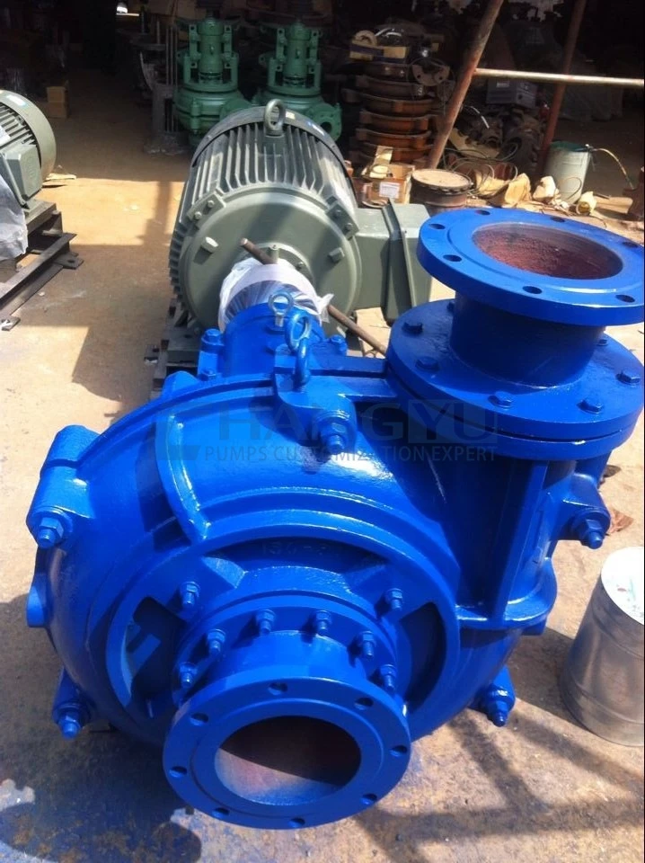
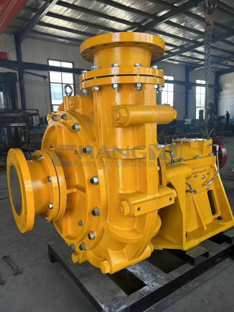
Série PGY — Bomba de Polpa de Alta Pressão para Serviço Pesado em Fluxo de Retorno de Fraturamento
Projetada para condições de alta pressão e desgaste severo. A construção de dupla carcaça permite a substituição das partes molhadas sem desmontar a tubulação — uma vantagem crítica em plataformas de poços congestionadas. O conjunto de rolamentos lubrificados a óleo garante confiabilidade de longo prazo sob operação contínua de alta carga. O design de alta pressão (até 101,6 m) permite a transferência direta da cabeça do poço para tanques de coleta centralizados sem bombas de reforço intermediárias — reduzindo a quantidade de equipamentos e simplificando a logística da plataforma.
| Parâmetro | Especificação |
|---|---|
| Caudal | 117–976 m³/h |
| Cabeça | 21,1–101,6 m |
| Potência do motor | 22–560 kW |
| Velocidade | 730 / 980 / 1.480 r/min |
| Materiais | BTMCr27 / BTMCr28 / BTMCr33 / aço inoxidável duplex |
Série HB — Bomba de Aço Inoxidável para Fluxo de Retorno Corrosivo
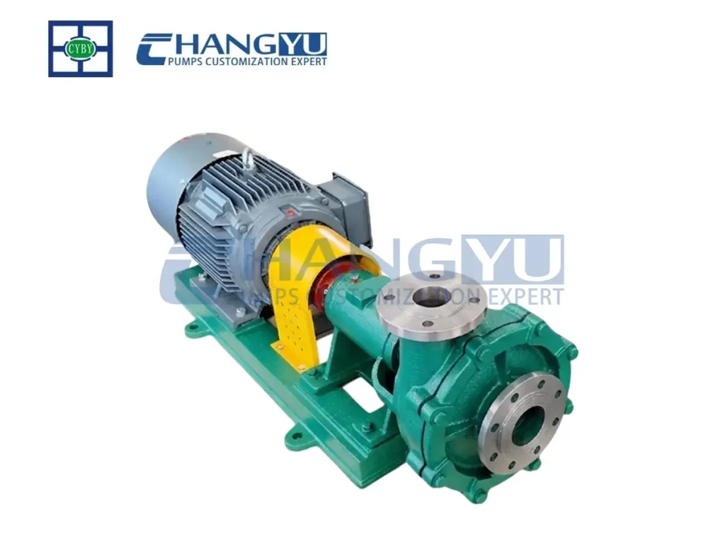
Bomba centrífuga horizontal conforme ISO 2858 com construção molhada totalmente em aço inoxidável. Disponível em 316L, duplex 2205 e super duplex 2507. Adequada para fluxo de retorno com aditivos químicos, retornos de estimulação ácida ou água produzida com cloretos elevados.
| Parâmetro | Especificação |
|---|---|
| Caudal | 10-60 m³/h |
| Cabeça | 20-120 m |
| Potência do motor | 3-45 kW |
| Velocidade | 2.900 r/min |
| Temperatura | -20°C a 120°C |
| Materiais | 304 / 316L / 2205 / 2507 |
Série UHB — Bomba Revestida em UHMW-PE para Serviço Econômico de Fluxo de Retorno
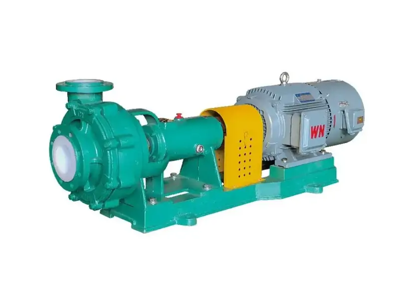
Bomba centrífuga revestida em UHMW-PE com estrutura de aço para fluxo de retorno em estágio tardio e água produzida com teor moderado de areia. O UHMW-PE oferece resistência combinada à corrosão e resistência superior à abrasão a um custo menor do que bombas totalmente metálicas. O impulsor semiaberto lida com sólidos residuais.
| Parâmetro | Especificação |
|---|---|
| Caudal | 3-2,600 m³/h |
| Cabeça | 5-100 m |
| Potência do motor | 0,75-300 kW |
| Velocidade | 750-2.900 r/min |
| Temperatura | -20°C a 90°C |
| Material do forro | UHMW-PE |
Perguntas Frequentes sobre Bombas de Polpa para Fluxo de Retorno de Fraturamento
P: Qual material dura mais em serviço de bomba de fluxo de retorno de fraturamento?
R: Revestimentos de carboneto de tungstênio e cerâmica (SiC) proporcionam 6 a 12 meses de vida útil em fluxo de retorno de alta velocidade e alto teor de areia, em comparação com 3 a 4 semanas para o Cr27 alto cromo. O carboneto de tungstênio oferece melhor resistência ao impacto onde há recortes de formação angulares; os revestimentos cerâmicos são mais adequados para fluxo de retorno com partículas finas e risco mínimo de impacto.
P: Por que o impulsor da minha bomba de fluxo de retorno se desgasta tão rapidamente?
R: A taxa de desgaste abrasivo em bombas de fluxo de retorno de fraturamento é proporcional ao cubo da velocidade do fluxo — dobrar a velocidade aumenta o desgaste em aproximadamente 8 vezes. Se sua bomba estiver operando no limite superior da faixa de vazão com altas concentrações de areia, a atualização para revestimentos de carboneto de tungstênio ou cerâmica é a solução mais eficaz.
P: Como evitar falhas no selo da bomba de fluxo de retorno?
R: Para plataformas de poços com água limpa, instale o plano API 32 de lavagem externa para evitar que a areia atinja as faces do selo. Para plataformas de poços remotas sem água confiável, selos centrífugos expulsores com gaxeta eliminam completamente a dependência de água externa. Para locais ambientalmente sensíveis, selos duplos API Plan 53C com monitoramento de pressão do fluido de barreira oferecem o mais alto nível de proteção contra vazamentos.
P: Posso usar a mesma bomba para fluxo de retorno em estágio inicial e tardio?
R: O fluxo de retorno em estágio inicial com pico de areia e gás requer impulsores de vórtice e máxima resistência ao desgaste. O fluxo de retorno em estágio tardio com sólidos residuais permite impulsores semiabertos de maior eficiência. Usar dois tipos de bomba — um dedicado ao estágio inicial, outro para serviço contínuo — otimiza tanto a confiabilidade quanto a eficiência.
P: Como devo armazenar bombas de fluxo de retorno entre os estágios de fraturamento?
R: Lave a bomba com água limpa antes de qualquer período de inatividade superior a 48 horas. Gire o eixo semanalmente para evitar a aderência das faces do selo e redistribuir o lubrificante dos rolamentos. Verifique a rotação livre do eixo antes de reiniciar.
P: Qual é a vantagem do design de dupla carcaça da Série PGY para fluxo de retorno?
R: O design de dupla carcaça permite a substituição dos componentes de desgaste molhados sem desconectar a tubulação de sucção e descarga — uma economia significativa de tempo em plataformas de poços congestionadas onde as trocas de bomba são difíceis.
Lista de verificação de prevenção do engenheiro de bombas da Changyu
- Não especifique Cr27 alto cromo para fluxo de retorno em estágio inicial com altas concentrações de areia e velocidades. O Cr33/Cr33M alto cromo é o mínimo; o carboneto de tungstênio oferece a melhor resistência ao impacto para condições de pico de areia.
- Calcule a velocidade real do fluxo na bomba — não apenas a velocidade na tubulação. A taxa de desgaste abrasivo aumenta com o cubo da velocidade. Superdimensionar a bomba para “estar seguro” na verdade acelera o desgaste ao aumentar as velocidades internas.
- Para plataformas de poços remotas sem água limpa confiável, especifique selos centrífugos expulsores com gaxeta. Não dependa de caminhões-pipa para lavagem do selo — uma única entrega perdida causa falha catastrófica do selo.
- Instale controle VFD para capacidade de partida suave e correspondência de vazão. A partida direta na linha com areia sedimentada na carcaça causa choque mecânico excessivo. Configure uma rampa de 15 a 30 segundos para bombas grandes (>100 kW); 5 a 10 segundos para bombas menores.
- Implemente um procedimento de lavagem com água doce antes de qualquer parada superior a 48 horas. Areia e produtos químicos residuais na carcaça causam corrosão e problemas de reinicialização.
- Gire o eixo da bomba semanalmente durante períodos prolongados de inatividade. Isso evita a aderência das faces do selo — uma causa comum de falha na reinicialização.
- Para plataformas de múltiplos poços, padronize dois tipos de bomba: um para fluxo de retorno em estágio inicial (revestido em carboneto de tungstênio, impulsor de vórtice, selo centrífugo expulsor) e um para água produzida contínua (Cr33 alto cromo, impulsor semiaberto, maior eficiência).
- Para instalações API Plan 53C, instale um manômetro e alarme de baixa pressão no reservatório de fluido de barreira. Uma perda de pressão de barreira significa que o selo interno está vazando e a bomba deve ser removida para substituição do selo antes que o selo externo falhe.
Conclusão
Uma bomba de polpa para fluxo de retorno de fraturamento é uma bomba especificamente projetada para uma das aplicações mais abrasivas e operacionalmente exigentes da indústria de petróleo e gás. Três fatores determinam a confiabilidade da bomba e o tempo de atividade produtiva: seleção de material compatível com a concentração de areia e velocidade do fluxo, design do impulsor que lida tanto com sólidos quanto com gás arrastado, e proteção do selo que funciona de forma confiável em condições remotas de plataforma de poço.
Para o fluxo de retorno em estágio inicial com pico de areia, revestimentos de carboneto de tungstênio fornecem a resistência ao impacto e a vida útil ao desgaste que ligas de alto cromo padrão não conseguem igualar. Selos centrífugos expeller eliminam a dependência de água de lavagem que torna os selos mecânicos convencionais não confiáveis em plataformas de poços remotos. Procedimentos de lavagem com água doce e rotação semanal do eixo durante períodos de inatividade previnem a corrosão e o travamento do selo que causam falhas na reinicialização.
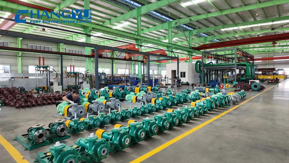
Quando você estiver pronto para especificar uma bomba de fluxo de retorno para suas operações de fraturamento, a equipe de engenharia da Changyu Pump pode fornecer uma avaliação técnica abrangendo caracterização da areia, recomendação de material e configuração de selo adequada às condições específicas da sua plataforma de poço. Duas décadas de fabricação de bombas resistentes ao desgaste nas indústrias de mineração, química e de campos petrolíferos embasam cada recomendação.