
Trả lời nhanh
Chọn đúng bơm bùn hồi lưu thủy lực nứt vỉa yêu cầu lựa chọn vật liệu phù hợp với độ mài mòn cực cao từ cát nứt vỉa, chọn thiết kế bánh công tác chống tắc nghẽn và xử lý khí cuốn theo, và xác định vòng đệm chịu được bùn mài mòn trong điều kiện mỏ dầu xa xôi. Cát nứt vỉa (độ cứng Mohs 7, kích thước hạt lên đến 840 μm) ở tốc độ dòng chảy cao có thể mài mòn qua bánh công tác hợp kim crôm cao tiêu chuẩn trong vòng 3–4 tuần. Lớp lót gốm kéo dài tuổi thọ lên 6–12 tháng trong cùng điều kiện. Bốn yếu tố lựa chọn cốt lõi:
- Khả năng chống mài mòn nghiêm trọng của vật liệu: Chất lỏng hồi lưu mang nồng độ cao cát silica và mảnh vụn đá vỉa góc cạnh. Tốc độ mài mòn tỷ lệ thuận với lập phương của vận tốc dòng chảy — tăng gấp đôi tốc độ dòng chảy làm tăng độ mài mòn khoảng 8 lần. Hợp kim crôm cao Cr33/Cr33M cung cấp nền tảng cơ bản cho điều kiện vừa phải; lớp lót cacbua vonfram và gốm mang lại tuổi thọ dài hơn đáng kể trong dịch vụ tốc độ cao, nhiều cát.
- Thiết kế bánh công tác cho chất rắn và khí: Chất lỏng hồi lưu thường chứa khí tự nhiên cuốn theo có thể gây kẹt hơi. Bánh công tác xoáy cung cấp khả năng chống tắc nghẽn tối đa cho chất rắn không thể đoán trước và xử lý khí một phần; bánh công tác nửa hở cân bằng khả năng dẫn chất rắn với hiệu suất cao hơn.
- Tính toàn vẹn của vòng đệm trong dịch vụ mài mòn: Các hạt cát phá hủy vòng đệm tiêu chuẩn với một buồng dầu ở giữa chúng — dầu cung cấp chất bôi trơn và có thể được theo dõi để phát hiện nước xâm nhập, cung cấp cảnh báo sớm về sự cố phớt dưới. trong vòng vài ngày. Vòng đệm cơ khí kép với xả ngoài API Plan 32 cung cấp khả năng làm kín đáng tin cậy khi có nước sạch. Đối với các giàn khoan xa xôi không có nước xả đáng tin cậy, vòng đệm ly tâm loại bỏ hoàn toàn sự phụ thuộc vào nước bên ngoài.
- Thích ứng với vận hành mỏ dầu gián đoạn: Máy bơm hồi lưu thủy lực nứt vỉa hoạt động theo lịch trình không đều — làm việc liên tục trong thời gian hồi lưu cao điểm, sau đó ngừng hoạt động trong nhiều tuần. Xả bằng nước sạch trước khi tắt máy và xoay trục hàng tuần trong thời gian ngừng hoạt động ngăn ngừa ăn mòn và dính bề mặt vòng đệm.
Hồi lưu thủy lực nứt vỉa là một trong những ứng dụng bơm khắc nghiệt nhất trong ngành dầu khí. Chất lỏng mang nồng độ cao cát silica hoặc chất chống đỡ gốm — cùng loại vật liệu dùng để nứt vỉa đá phiến — nay quay trở lại bề mặt với tốc độ cao. Mỗi hạt cát đi qua máy bơm hoạt động như một dụng cụ cắt, làm xói mòn bánh công tác, vỏ bơm và vòng đệm. Thêm vào thách thức, mảnh vụn đá vỉa góc cạnh và cặn bùn khoan tạo ra hiệu ứng mài mòn hỗn hợp nghiêm trọng hơn so với chỉ chất chống đỡ tròn. Một máy bơm bùn tiêu chuẩn có thể yêu cầu thay thế phần ướt trong vòng vài tuần, trong khi máy bơm với vật liệu được xác định không chính xác có thể hỏng trong vài ngày.
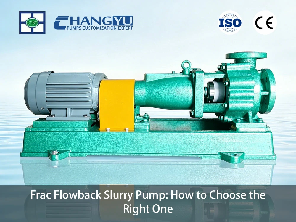
Changyu Pump đã sản xuất máy bơm chống mài mòn cho các ứng dụng khai thác mỏ, hóa chất và mỏ dầu trong hơn hai thập kỷ. Hướng dẫn này bao gồm lựa chọn vật liệu, thiết kế bánh công tác, bảo vệ vòng đệm và thực hành vận hành quyết định liệu máy bơm bùn hồi lưu thủy lực nứt vỉa có tồn tại qua mùa nứt vỉa hay trở thành chi phí thay thế định kỳ.
Máy Bơm Bùn Hồi Lưu Thủy Lực Nứt Vỉa Là Gì và Tại Sao Nó Khác Biệt?
Máy bơm bùn hồi lưu thủy lực nứt vỉa xử lý chất lỏng quay trở lại bề mặt sau khi nứt vỉa thủy lực. Chất lỏng hồi lưu này là hỗn hợp của dung dịch nứt vỉa được bơm vào, nước vỉa, chất chống đỡ (hạt cát hoặc gốm), mảnh vụn đá vỉa góc cạnh, cặn bùn khoan và phụ gia hóa học. Máy bơm phải hoạt động dưới tốc độ dòng chảy cao, điều kiện áp suất thay đổi và — trong nhiều trường hợp — vị trí giàn khoan xa xôi với khả năng bảo trì hạn chế.
Đặc Điểm Chính của Chất Lỏng Hồi Lưu Thủy Lực Nứt Vỉa
- Nồng độ chất rắn cao: Tải lượng chất chống đỡ có thể dao động từ dấu vết đến hơn 10% thể tích trong thời gian hồi lưu cát cao điểm. Kích thước hạt dao động từ mịn (100 mesh, ~150 μm) đến thô (20/40 mesh, ~420–840 μm).
- Độ cứng hạt mài mòn: Cát nứt vỉa chủ yếu là thạch anh (độ cứng Mohs 7, khoảng 800–1.000 HV). Chất chống đỡ gốm có thể đạt độ cứng Mohs 9.
- Mài mòn hỗn hợp từ chất rắn hỗn hợp: Ngoài cát nứt vỉa hình cầu, chất lỏng hồi lưu thường chứa mảnh vụn đá vỉa góc cạnh và cặn bùn khoan. Các hạt không đều này gây ra mài mòn cắt nghiêm trọng hơn so với chất chống đỡ tròn có cùng độ cứng, vì các cạnh sắc của chúng tập trung lực lên các diện tích tiếp xúc nhỏ hơn.
- Điều kiện dòng chảy thay đổi: Tốc độ hồi lưu giảm dần theo thời gian khi áp suất vỉa cạn kiệt. Máy bơm phải hoạt động hiệu quả trên một phạm vi dòng chảy rộng.
- Khí cuốn theo: Khí tự nhiên, carbon dioxide và hydro sulfide có thể có trong chất lỏng hồi lưu, gây kẹt hơi trong máy bơm không được thiết kế để xử lý khí.
- Vận hành gián đoạn: Hồi lưu vốn không liên tục — máy bơm có thể chạy 24/7 trong nhiều ngày, sau đó ngừng hoạt động trong nhiều tuần giữa các giai đoạn nứt vỉa.
Khác Biệt Chính So Với Máy Bơm Bùn Tiêu Chuẩn
Bảng: Máy Bơm Bùn Hồi Lưu Thủy Lực Nứt Vỉa vs Máy Bơm Bùn Tiêu Chuẩn
| Tính năng | Bơm bùn tiêu chuẩn | Máy Bơm Bùn Hồi Lưu Thủy Lực Nứt Vỉa |
|---|---|---|
| Vật liệu tiếp xúc với chất lỏng | Hợp kim có hàm lượng crom cao hoặc cao su | Lớp lót hợp kim crôm cao Cr33/Cr33M, cacbua vonfram hoặc gốm |
| Cánh quạt | Kín hoặc nửa hở | Bánh công tác xoáy hoặc nửa hở với xử lý chống mài mòn |
| Vòng đệm | Vòng đệm cơ khí đơn | Vòng đệm cơ khí kép với xả ngoài API Plan 32 hoặc vòng đệm ly tâm |
| Xử lý khí | Không có | Xử lý khí một phần qua thiết kế bánh công tác hở hoặc xoáy |
| Bộ ổ trục | Tiêu chuẩn | Quá khổ cho hoạt động liên tục tải cao |
| Mô hình vận hành | Hoạt động liên tục | Gián đoạn — được thiết kế cho khởi động/dừng thường xuyên và thời gian ngừng hoạt động |
Vật Liệu Nào Chống Mài Mòn Trong Máy Bơm Bùn Hồi Lưu Thủy Lực Nứt Vỉa?
Lựa chọn vật liệu là quyết định quan trọng nhất đối với máy bơm bùn hồi lưu thủy lực nứt vỉa. Sự kết hợp của các hạt cát tốc độ cao, mảnh vụn đá vỉa góc cạnh và phụ gia hóa học tạo ra môi trường mài mòn cực độ mà vật liệu máy bơm tiêu chuẩn không thể chịu được.
Cách Hồi Lưu Thủy Lực Nứt Vỉa Tấn Công Vật Liệu Máy Bơm
Các hạt cát nứt vỉa có góc cạnh và cứng (độ cứng Mohs 7). Khi các hạt này va đập vào bề mặt máy bơm ở tốc độ cao — đặc biệt tại đầu cánh bánh công tác và lưỡi cắt thân bơm — chúng cắt vào vật liệu, loại bỏ kim loại sau mỗi lần tiếp xúc.
The mài mòn Tốc độ mài mòn tỷ lệ thuận với lập phương của vận tốc dòng chảy — tăng gấp đôi tốc độ dòng chảy làm tăng độ mài mòn khoảng 8 lần. Điều này giải thích tại sao các máy bơm xử lý nồng độ cát tương tự có thể trải qua tuổi thọ dịch vụ khác nhau đáng kể tùy thuộc vào vận tốc dòng chảy trong máy bơm.
Các mảnh cắt có góc cạnh làm tăng thêm hiệu ứng này. Không giống như các hạt chất độn tròn có thể lăn trên bề mặt bơm, các mảnh cắt sắc cạnh tập trung lực va đập vào các diện tích tiếp xúc nhỏ, khoét vật liệu khỏi bề mặt thay vì làm mòn dần dần.
Các Lựa Chọn Vật Liệu Cho Dịch Vụ Frac Flowback
Bảng: Lựa Chọn Vật Liệu Cho Bơm Bùn Frac Flowback
| Chất liệu | Tuổi Thọ Dịch Vụ Điển Hình Trong Frac Flowback | Phù hợp nhất cho | Hạn chế |
|---|---|---|---|
| Cao-Crôm Cr27 (650–700 HB) | 3–6 tuần (vận tốc cao); 8–12 tuần (vận tốc thấp) | Ít cát, vận tốc thấp, hạn chế ngân sách | Mòn nhanh trong cát vận tốc cao; ăn mòn dưới pH 4 |
| Cao-Crôm Cr33/Cr33M (700–750 HB) | 6–12 tuần (vận tốc cao); 12–20 tuần (vận tốc thấp) | Cát và vận tốc trung bình | Chi phí cao hơn Cr27; vẫn bị mòn trong điều kiện khắc nghiệt |
| Lớp Lót Carbua Vonfram (HV 1200–1800) | 6–12 tháng | Dòng chảy ngược vận tốc cao, hạt mịn; được ưu tiên cho khả năng chống va đập | Chi phí cao hơn; có thể nứt vỡ dưới tác động của các mảnh cắt rất lớn |
| Lớp Lót Gốm — SiC (HV 2200–2800) | 6–12 tháng (hạt mịn, va đập thấp); 3–6 tháng (hạt thô có nguy cơ va đập) | Vận tốc cao, cát mịn với va đập tối thiểu | Nguy cơ nứt vỡ giòn từ các hạt trên 2 mm hoặc mảnh cắt có góc cạnh |
| Vật Liệu Tổng Hợp Gốm-Cao Su | 6–12 tháng | Kích thước hạt hỗn hợp có nguy cơ va đập | Chi phí cao hơn; lớp nền cao su hấp thụ năng lượng va đập |
| Lót UHMW-PE | 2–4 tháng với mảnh cắt có góc cạnh; 3–6 tháng chỉ với cát tròn | Vận tốc thấp, cát trung bình với hạt tròn | Giới hạn nhiệt độ 90°C; không dùng cho cát thô vận tốc cao hoặc mảnh cắt có góc cạnh |
Phù Hợp Vật Liệu Theo Điều Kiện Flowback
Bảng: Phù Hợp Vật Liệu Theo Điều Kiện Flowback
| Điều Kiện Flowback | Nồng Độ Cát | Vận Tốc Dòng Chảy | Tài liệu tham khảo |
|---|---|---|---|
| Flowback giai đoạn đầu (cát đỉnh) | Cao (> 5% theo thể tích) | Cao (> 5 m/s) | Carbua vonfram (ưu tiên cho khả năng chống va đập) hoặc lớp lót gốm (cho dòng chảy ngược hạt mịn, va đập thấp) |
| Flowback giai đoạn giữa (cát giảm dần) | Trung bình (2–5%) | Trung bình (3–5 m/s) | Cao-crôm Cr33/Cr33M |
| Flowback giai đoạn cuối (cát vết) | Thấp (< 2%) | Thấp đến trung bình | Cao-crôm Cr27 hoặc lót UHMW-PE |
| Flowback với phụ gia hóa học | Biến | Biến | Duplex 2205 (chống ăn mòn) hoặc lót FEP/PFA |
Các kỹ sư tại Changyu Pump đã quan sát thấy trên các hệ thống lắp đặt bơm frac flowback: Đối với flowback giai đoạn đầu với nồng độ cát đỉnh và vận tốc cao, cao-crôm Cr27 không phải là vật liệu đầy đủ — mòn bánh công tác trong vòng 3–4 tuần là phổ biến. Nâng cấp lên cao-crôm Cr33/Cr33M mang lại cải thiện từng bước, nhưng sự kéo dài tuổi thọ đáng kể nhất đến từ lớp lót carbua vonfram hoặc gốm, có thể kéo dài tuổi thọ dịch vụ từ vài tuần lên vài tháng. Phí bảo hiểm chi phí vật liệu thường được thu hồi trong hai giai đoạn bẻ gãy đầu tiên nhờ loại bỏ việc thay thế bơm và giảm thời gian không sản xuất.
Tại Sao Thiết Kế Bánh Công Tác Lại Quan Trọng Đối Với Bơm Bùn Frac Flowback?
Chất lỏng flowback đặt ra một thách thức kép cho thiết kế bánh công tác: chất rắn mài mòn làm tắc các kênh hẹp và khí cuốn theo gây ra hiện tượng kẹt hơi. Việc lựa chọn bánh công tác phải giải quyết đồng thời cả hai chế độ hỏng hóc.
Các Loại Bánh Công Tác Cho Dịch Vụ Flowback
Bánh Công Tác Dạng Xoáy (Lõm):
Bánh công tác nằm lõm vào thành sau của buồng xoắn, tạo ra một dòng xoáy hút chất lỏng và chất rắn qua bơm. Chỉ một phần chất lỏng tiếp xúc trực tiếp với bánh công tác, mang lại khe hở tự do lớn nhất cho chất rắn và gần như miễn nhiễm với tắc nghẽn. Thiết kế xoáy cũng cung cấp khả năng xử lý khí một phần — các bong bóng khí cuốn theo đi qua mà không gây ra kẹt hơi. Hiệu suất thấp hơn (35–55%), nhưng đối với flowback giai đoạn đầu với chất rắn và khí không thể đoán trước, độ tin cậy quan trọng hơn tổn thất năng lượng.
Cánh quạt bán mở:
Các cánh bánh công tác được gắn vào một đĩa sau mà không có đĩa trước. Mặt hở cho phép chất rắn đi qua mà không bị thắt chặt như các thiết kế kín. Hiệu suất cao hơn loại xoáy (50–60%). Phù hợp cho flowback giai đoạn giữa đến cuối, nơi hàm lượng chất rắn thấp hơn và phần khí giảm. Bánh công tác nửa hở có thể được chế tạo với vật liệu chống mài mòn hoặc lớp phủ để kéo dài tuổi thọ dịch vụ.
Bánh Công Tác Kênh:
Một hoặc hai kênh rộng duy nhất xuyên qua bánh công tác chứa chất rắn. Hiệu suất cao hơn (55–70%) so với thiết kế xoáy hoặc nửa hở. Phù hợp cho flowback giai đoạn cuối hoặc chuyển nước khai thác, nơi hàm lượng chất rắn thấp và có thể dự đoán được.
Chiến Lược Xử Lý Khí Cho Bơm Flowback
Khi chất lỏng flowback chứa một lượng khí cuốn theo đáng kể, bơm phải được cấu hình để ngăn ngừa kẹt hơi — một tình trạng khí tích tụ trong mắt bánh công tác, chặn dòng chảy chất lỏng.
- Lắp đặt bơm thẳng đứng: Khí tự nhiên bay lên đỉnh vỏ bơm và thoát ra qua cửa xả. Bơm thẳng đứng có khả năng tự xả khí vốn có.
- Van xả khí tự động: Được lắp đặt tại điểm cao nhất của vỏ bơm hoặc đường ống xả để xả khí tích tụ một cách tự động.
- Bánh công tác xoáy hoặc hở: Các thiết kế này cho phép khí đi qua nhiều hơn so với bánh công tác kín. Đặc biệt, bánh công tác xoáy có thể xử lý tới 20% khí theo thể tích mà không mất mồi.
Lựa Chọn Bánh Công Tác Theo Giai Đoạn Flowback
Bảng: Lựa Chọn Bánh Công Tác Theo Giai Đoạn Flowback
| Giai Đoạn Flowback | Hàm lượng chất rắn | Phần Khí | Bánh Công Tác Được Khuyến Nghị |
|---|---|---|---|
| Giai đoạn đầu (cát đỉnh) | Cao, không thể đoán trước | Cao | Vòng xoáy |
| Giai đoạn giữa (cát giảm dần) | Trung bình | Trung bình | Nửa hở hoặc vortex |
| Giai đoạn cuối (cát vết) | Thấp | Thấp | Nửa hở hoặc kênh |
| Chuyển nước khai thác | Rất thấp | Thấp | Kênh |
Khớp công suất động cơ với công suất tiêu thụ của bơm tại điểm vận hành cộng với biên độ an toàn. Đối với nhiệm vụ liên tục, chỉ định hệ số dịch vụ tối thiểu 1,15. Đối với dịch vụ chất lỏng dễ cháy, chỉ định động cơ chống nổ với chứng nhận ATEX hoặc IECEx phù hợp với phân loại khu vực nguy hiểm. Trong 2–4 tuần đầu tiên của flowback khi cát hồi lưu đạt đỉnh và khí phổ biến nhất, bánh công tác xoáy mang lại rủi ro thấp nhất về tắc nghẽn và kẹt hơi. Khi flowback chuyển sang điều kiện cát và khí thấp hơn, bánh công tác nửa hở mang lại hiệu suất cao hơn cho việc xử lý nước khai thác lâu dài. Cân nhắc giữ một bơm bánh công tác xoáy chuyên dụng cho flowback giai đoạn đầu và một bơm bánh công tác nửa hở riêng cho dịch vụ nước khai thác liên tục — thời gian ngừng hoạt động tránh được từ một lần tắc bơm duy nhất sẽ bù đắp chi phí thiết bị.

Làm Thế Nào Để Ngăn Ngừa Hỏng Phớt Trong Bơm Bùn Frac Flowback?
The phốt cơ khí là điểm hỏng hóc phổ biến nhất trên bơm frac flowback. Các hạt cát xâm nhập vào buồng phớt hoạt động như một hợp chất mài mòn giữa các bề mặt phớt, phá hủy chúng trong vòng vài ngày nếu không có biện pháp bảo vệ.
Thách Thức Về Phớt Trong Dịch Vụ Flowback
- Sự xâm nhập của hạt mài mòn: Các hạt cát mịn (100 mesh và nhỏ hơn) xâm nhập vào buồng phốt, bám vào các bề mặt phốt và gây mài mòn nhanh chóng.
- Điều kiện áp suất thay đổi: Áp suất dòng chảy ngược thay đổi khi giếng cạn kiệt, khiến tải trọng lên bề mặt phốt dao động.
- Vận hành gián đoạn: Trong thời gian ngừng hoạt động, các chất rắn còn sót lại trong buồng phốt có thể lắng đọng và kết dính các bề mặt phốt với nhau, gây hư hỏng khi khởi động lại.
- Hạn chế về vị trí xa xôi: Nhiều giàn khoan thiếu nguồn cấp nước sạch đáng tin cậy cho hệ thống xả phốt thông thường.
Giải pháp Phốt cho Bơm Dòng chảy Ngược Thủy lực
API Plan 32 — Xả Nước Sạch Bên ngoài:
Một dòng nước sạch liên tục được bơm vào buồng phốt ở áp suất cao hơn áp suất buồng phốt 1–2 bar. Điều này tạo ra một hàng rào chất lỏng sạch tại các bề mặt phốt, ngăn các hạt cát tiếp xúc với phốt. Lưu lượng thường là 4–12 L/phút. Giải pháp này đáng tin cậy khi có sẵn nước xả sạch, nhưng nhiều giàn khoan xa xôi lại thiếu cơ sở hạ tầng cấp nước và xử lý để hỗ trợ.
Bộ đẩy ly tâm (Phốt động) với Đệm nhồi:
Khi không có nước xả sạch — thường gặp ở các giàn khoan xa xôi — bộ đẩy ly tâm kết hợp với đệm nhồi cung cấp khả năng làm kín hiệu quả mà không cần nguồn nước bên ngoài. Bộ đẩy là một bánh công tác hở nhỏ được gắn phía sau bánh công tác chính. Trong quá trình vận hành bơm, bộ đẩy tạo ra chênh lệch áp suất đẩy chất lỏng chứa cát ra xa buồng phốt. Trong thời gian chờ, đệm nhồi cung cấp phốt tĩnh.
Sự sắp xếp này mang lại một lợi thế quan trọng cho các ứng dụng dòng chảy ngược thủy lực: nó loại bỏ hoàn toàn sự phụ thuộc vào nước xả bên ngoài. Không cần xe bồn nước, không cần hệ thống lọc, không cần bảo vệ chống đóng băng — chỉ cần bản thân máy bơm duy trì tính toàn vẹn của phốt.
API Plan 53C — Phớt Kép với Chất lỏng Chắn Có Áp suất:
Một phốt cơ khí kép với bình chứa chất lỏng màng ngăn có áp suất. Áp suất màng ngăn vượt quá áp suất buồng phốt, ngăn chất lỏng quy trình tiếp cận các bề mặt phốt. Phù hợp cho các vị trí nhạy cảm với môi trường, nơi bất kỳ sự rò rỉ quy trình nào cũng không thể chấp nhận được. Lắp đặt đồng hồ đo áp suất và báo động áp suất thấp trên bình chứa chất lỏng màng ngăn để cảnh báo ngay lập tức về sự mất mát chất lỏng màng ngăn — mất áp suất màng ngăn có nghĩa là phốt bên trong đang bị rò rỉ và máy bơm cần được tháo ra để thay thế phốt trước khi phốt bên ngoài bị hỏng.
Lựa chọn Phốt cho Ứng dụng Dòng chảy Ngược
Bảng: Lựa chọn Phốt cho Ứng dụng Dòng chảy Ngược
| Điều kiện Giàn khoan | Phớt được khuyến nghị | Lý do |
|---|---|---|
| Có sẵn nước xả sạch | Phốt kép API Plan 32 | Bảo vệ bề mặt phốt đáng tin cậy nhất |
| Không có nước xả (giàn khoan xa xôi) | Bộ đẩy ly tâm + đệm nhồi | Không cần nước bên ngoài |
| Khu vực nhạy cảm với môi trường | Phốt kép API Plan 53C | Không rò rỉ quy trình; yêu cầu báo động áp suất |
| Dòng chảy ngược có tỷ lệ khí cao | Bộ đẩy ly tâm + đệm nhồi | Chịu được chạy khô gián đoạn tốt hơn phốt cơ khí |
Khớp công suất động cơ với công suất tiêu thụ của bơm tại điểm vận hành cộng với biên độ an toàn. Đối với nhiệm vụ liên tục, chỉ định hệ số dịch vụ tối thiểu 1,15. Đối với dịch vụ chất lỏng dễ cháy, chỉ định động cơ chống nổ với chứng nhận ATEX hoặc IECEx phù hợp với phân loại khu vực nguy hiểm. Đối với các giàn khoan xa xôi không có nước sạch đáng tin cậy — phần lớn các ứng dụng dòng chảy ngược thủy lực — phốt bộ đẩy ly tâm với đệm nhồi cung cấp giải pháp làm kín thực tế và hiệu quả nhất về chi phí. Việc loại bỏ sự phụ thuộc vào nước xả làm giảm độ phức tạp về hậu cần và loại bỏ nguy cơ hỏng phốt do gián đoạn nước xả. Đối với các vị trí nhạy cảm với môi trường, phốt kép API Plan 53C với giám sát chất lỏng màng ngăn thường xuyên cung cấp khả năng bảo vệ chống rò rỉ cần thiết.
Làm thế nào để Điều chỉnh Bơm Bùn Dòng chảy Ngược Thủy lực cho các Điều kiện Mỏ dầu Thay đổi?
Bơm dòng chảy ngược thủy lực hoạt động trong các điều kiện về cơ bản khác với bơm công nghiệp ở trạng thái ổn định. Bản chất gián đoạn của các hoạt động bẻ gãy thủy lực — vận hành liên tục trong thời gian dòng chảy ngược đỉnh điểm, sau đó là thời gian ngừng hoạt động kéo dài — tạo ra những thách thức cần được giải quyết thông qua cả thông số kỹ thuật thiết bị và kỷ luật vận hành.
Thách thức của Vận hành Mỏ dầu Gián đoạn
- Khởi động và dừng thường xuyên: Mỗi lần khởi động bơm gây ra sốc cơ học lên vòng bi, phốt và khớp nối. Cát lắng đọng trong vỏ bơm làm tăng mô-men xoắn khởi động.
- Biến động lưu lượng lớn: Tốc độ dòng chảy ngược giảm từ đỉnh điểm ban đầu xuống gần như bằng không trong vài tuần. Máy bơm phải hoạt động hiệu quả trên một dải lưu lượng rộng mà không bị quá nhiệt ở lưu lượng thấp.
- Thời gian ngừng hoạt động kéo dài: Máy bơm có thể ngừng hoạt động trong nhiều tuần giữa các giai đoạn bẻ gãy. Chất lỏng dòng chảy ngược còn sót lại trong vỏ bơm gây ăn mòn, và sự lắng đọng chất rắn có thể kết dính các bộ phận bên trong.
- Hạn chế về vị trí xa xôi: Khả năng tiếp cận hạn chế với các tiện ích, nước và nhân viên bảo trì có nghĩa là máy bơm phải tự túc và yêu cầu can thiệp tối thiểu.
Thông số Kỹ thuật Thiết bị cho Nhiệm vụ Mỏ dầu
- Điều khiển VFD với phản hồi lưu lượng: Điều chỉnh tốc độ bơm để phù hợp với tốc độ dòng chảy ngược thực tế, ngăn ngừa vận hành ở chế độ đóng van hoặc lưu lượng quá mức. VFD cũng cung cấp khả năng khởi động mềm — cấu hình thời gian tăng tốc 15–30 giây cho máy bơm lớn (>100 kW) để giảm sốc cơ học; 5–10 giây cho máy bơm nhỏ hơn.
- Vòng bi quá khổ: Vòng bi được định mức cho tải trọng hướng tâm tối đa dự kiến với hệ số dịch vụ ít nhất là 1,5 cho dịch vụ nặng gián đoạn.
- Đế bơm và khớp nối gia cố: Được thiết kế để chịu được rung động và lệch trục thường gặp trên các lắp đặt kiểu skid di động.
- Đường bypass lưu lượng tối thiểu: Một đường ống bypass nhỏ đưa một phần lưu lượng xả của bơm trở lại nguồn hút, đảm bảo lưu lượng làm mát tối thiểu qua bơm khi van xả chính bị tiết lưu.
Thực hành Vận hành để Kéo dài Tuổi thọ Bơm
- Xả bằng nước ngọt trước khi dừng: Khi máy bơm sẽ ngừng hoạt động trong hơn 48 giờ, hãy xả vỏ bơm và đường ống bằng nước sạch để loại bỏ cát và phụ gia hóa học còn sót lại. Điều này ngăn ngừa ăn mòn trong thời gian ngừng hoạt động và đảm bảo máy bơm sẵn sàng khởi động lại ngay lập tức.
- Xoay trục hàng tuần trong thời gian ngừng hoạt động: Xoay trục bơm bằng tay mỗi tuần một lần ngăn các bề mặt phốt dính vào nhau và phân phối lại chất bôi trơn trên vòng bi. Quy trình đơn giản này làm giảm đáng kể sự cố khi khởi động lại.
- Kiểm tra sau thời gian ngừng hoạt động: Trước khi khởi động lại máy bơm đã ngừng hoạt động hơn hai tuần, hãy xác minh trục quay tự do bằng tay, kiểm tra mức và áp suất chất lỏng màng ngăn của phốt (nếu có), và xác nhận rằng van hút và van xả hoạt động chính xác.
Làm thế nào để chọn đúng bơm bùn dòng chảy ngược (Frac Flowback Slurry Pump) và tránh hỏng hóc sớm?
Việc lựa chọn bơm dòng chảy ngược (frac flowback pump) đòi hỏi phải kết hợp vật liệu, thiết kế bánh công tác, cấu hình phớt kín và các tính năng vận hành phù hợp với các điều kiện dòng chảy ngược cụ thể tại mỗi giếng hoặc cụm giếng.
Các vấn đề thường gặp và giải pháp cho bơm dòng chảy ngược (Frac Flowback Pump)
Bảng: Các vấn đề thường gặp và giải pháp cho bơm dòng chảy ngược (Frac Flowback Pump)
| Vấn đề | Nguyên nhân gốc rễ | Giải pháp |
|---|---|---|
| Bánh công tác bị mòn xuyên thủng trong 3–4 tuần | Cr27 hàm lượng crom cao không đủ khả năng chống cát vận tốc cao | Nâng cấp lên Cr33/Cr33M hàm lượng crom cao, cacbua vonfram hoặc lớp lót gốm |
| Bơm bị tắc liên tục | Bánh công tác kín giữ chất rắn; nồng độ chất rắn cao | Chuyển sang bánh công tác xoáy (vortex impeller) |
| Phớt kín cơ khí hỏng trong vòng vài ngày | Cát xâm nhập vào buồng phớt; không có hệ thống xả | Lắp đặt hệ thống xả API Plan 32 hoặc phớt kín ly tâm đẩy (centrifugal expeller seal) |
| Bơm mất mồi / khóa hơi (vapor lock) | Khí cuốn theo tích tụ tại mắt bánh công tác | Lắp đặt van xả khí tự động; sử dụng bánh công tác xoáy; cân nhắc bơm đứng |
| Rung động quá mức sau khi khởi động lại | Chất rắn lắng đọng gây mất cân bằng; các mặt phớt bị kẹt | Xả trước khi dừng; xoay trục hàng tuần trong thời gian ngừng hoạt động |
| Quá tải động cơ khi khởi động | Cát lắng đọng làm tăng mô-men xoắn khởi động | Xả bơm trước khi khởi động lại; lắp đặt biến tần VFD với khởi động mềm |
Quy trình lựa chọn bơm dòng chảy ngược sáu bước
Bước 1: Xác định đặc tính chất lỏng dòng chảy ngược.
Xác định dải nồng độ cát dự kiến, phân bố kích thước hạt (bao gồm cả mảnh vụn hệ tầng), sự hiện diện của các chất phụ gia hóa học, độ pH, nồng độ clorua và phần khí.
Bước 2: Xác định các yêu cầu thủy lực.
Tính toán lưu lượng yêu cầu (dựa trên tốc độ dòng chảy ngược đỉnh dự kiến và số lượng bơm), cột áp tổng (áp suất đầu giếng cộng với tổn thất ma sát đến bể thu gom) và NPSH khả dụng.
Bước 3: Chọn loại bánh công tác.
Bước 3: Chọn thiết kế bánh công tác.
Kết hợp thiết kế bánh công tác với các điều kiện khó khăn nhất dự kiến. Dòng chảy ngược giai đoạn đầu với hàm lượng cát và khí cao yêu cầu bánh công tác xoáy. Giai đoạn cuối với ít chất rắn cho phép sử dụng bánh công tác nửa hở để đạt hiệu suất cao hơn.
Bước 4: Chọn vật liệu.
Kết hợp vật liệu tiếp xúc chất lỏng với nồng độ cát, vận tốc dòng chảy và môi trường hóa học theo ma trận trong Phần 2. Đối với cát đỉnh ở vận tốc cao, cacbua vonfram cung cấp khả năng chống va đập tốt nhất; lớp lót gốm được ưu tiên cho các điều kiện hạt mịn, va đập thấp.
Bước 5: Xác định cấu hình phớt kín.
Chọn loại phớt kín dựa trên khả năng cấp nước và độ nhạy môi trường theo hướng dẫn trong Phần 4. Đối với hầu hết các cụm giếng xa, phớt kín ly tâm đẩy (centrifugal expeller seals) loại bỏ sự phụ thuộc vào nước.
Bước 6: Xác định các tính năng vận hành.
Khớp công suất động cơ với công suất tiêu thụ của bơm tại điểm vận hành cộng với biên độ an toàn. Đối với nhiệm vụ liên tục, chỉ định hệ số dịch vụ tối thiểu 1,15. Đối với dịch vụ chất lỏng dễ cháy, chỉ định động cơ chống nổ với chứng nhận ATEX hoặc IECEx phù hợp với phân loại khu vực nguy hiểm. Bao gồm VFD để khởi động mềm và điều chỉnh lưu lượng, kết nối xả nước ngọt, đường vòng lưu lượng tối thiểu để bảo vệ lưu lượng thấp, và — đối với hệ thống lắp đặt API Plan 53C — đồng hồ đo áp suất chất lỏng chắn với báo động áp suất thấp.
Đối với các cụm giếng nhiều giếng, tiêu chuẩn hóa một kiểu bơm cho dòng chảy ngược giai đoạn đầu (bánh công tác xoáy, lót cacbua vonfram, phớt kín ly tâm đẩy) và một kiểu hiệu suất cao hơn cho việc chuyển nước sản phẩm liên tục (bánh công tác nửa hở, Cr33/Cr33M hàm lượng crom cao, phớt kín API Plan 32 nếu có nước). Việc tiêu chuẩn hóa giúp giảm tồn kho phụ tùng thay thế trong khi vẫn bao phủ toàn bộ vòng đời dòng chảy ngược.
Nghiên cứu điển hình về bơm bùn dòng chảy ngược (Frac Flowback Slurry Pump): Giải quyết khủng hoảng tuổi thọ ngắn của bơm dòng chảy ngược.
Một nhà khai thác dầu đá phiến tại Mỹ đã vận hành ba bơm ly tâm trên một cụm giếng nhiều giếng xử lý dòng chảy ngược giai đoạn đầu. Thông số kỹ thuật ban đầu: các bộ phận tiếp xúc chất lỏng bằng Cr27 hàm lượng crom cao với phớt kín cơ khí đơn. Điều kiện dòng chảy ngược: nồng độ cát 5–8% theo thể tích, kích thước hạt 100–400 μm với các mảnh vụn hệ tầng góc cạnh, vận tốc dòng chảy 5–6 m/s tại bánh công tác, vận hành gián đoạn với thời gian ngừng hoạt động 2–3 tuần giữa các giai đoạn bẻ gãy thủy lực.
Các bơm yêu cầu thay thế bánh công tác mỗi 3–4 tuần. Phớt kín cơ khí hỏng trong vòng 10–14 ngày, với kiểm tra cho thấy cát bám vào các mặt phớt và các vết xước sâu. Mỗi lần thay bơm cần 4–6 giờ thời gian không sản xuất, trong thời gian đó dòng chảy ngược được chuyển hướng đến bể chứa khẩn cấp hoặc đốt bỏ.
- Phân tích nguyên nhân gốc rễ xác định ba điểm hỏng hóc:.
- Cr27 hàm lượng crom cao (650–700 HB) bị cắt bởi cát thạch anh (800–1.000 HV) ở vận tốc dòng chảy cao, với các mảnh vụn hệ tầng góc cạnh làm tăng tốc độ mài mòn.
- Phớt kín cơ khí đơn không có hệ thống xả cho phép cát mịn xâm nhập vào buồng phớt, phá hủy các mặt phớt.
Không có quy trình xả khi dừng khiến cát còn sót lại lắng đọng trong vỏ bơm trong thời gian ngừng hoạt động, gây mất cân bằng khi khởi động lại.
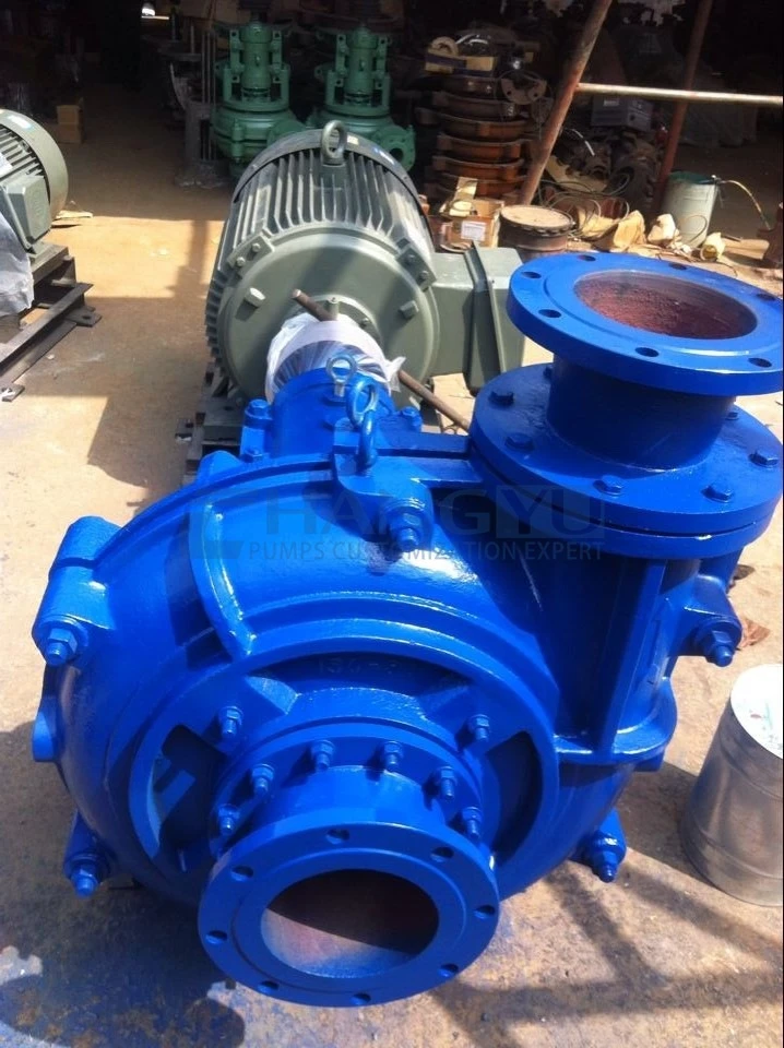
Nhà khai thác đã thay thế các bơm bằng dòng bơm Changyu PGY Series với các bộ phận tiếp xúc chất lỏng bằng Cr33M hàm lượng crom cao, có lớp phủ bánh công tác bằng cacbua vonfram và phớt kín ly tâm đẩy với đệm nhồi. Các kết nối xả nước ngọt đã được thêm vào, và một quy trình dừng đã được thực hiện: xả bằng nước sạch trong 10 phút trước bất kỳ thời gian ngừng hoạt động nào vượt quá 48 giờ.
Bài học chínhKết quả trong chiến dịch bẻ gãy thủy lực kéo dài sáu tháng: tuổi thọ bánh công tác kéo dài từ 3–4 tuần lên hơn 14 tuần. Không có hỏng hóc phớt kín cơ khí nào. Thời gian thay bơm đã được loại bỏ khỏi lộ trình quan trọng của các hoạt động dòng chảy ngược. Chi phí thay thế bơm đã được thu hồi trong hai giai đoạn bẻ gãy thủy lực đầu tiên nhờ loại bỏ thời gian không sản xuất và giảm bảo trì bơm.
: Trong dịch vụ dòng chảy ngược (frac flowback service), Cr27 hàm lượng crom cao với phớt kín cơ khí đơn không phải là thông số kỹ thuật đầy đủ cho các điều kiện cát đỉnh. Nâng cấp lên Cr33M hàm lượng crom cao với lớp phủ cacbua vonfram và phớt kín ly tâm đẩy — kết hợp với quy trình xả nước ngọt — kéo dài tuổi thọ bơm từ vài tuần lên vài tháng và loại bỏ hỏng hóc phớt kín như một nguồn gây thời gian không sản xuất.
Giải pháp bơm bùn dòng chảy ngược (Frac Flowback Slurry Pump) của Changyu Pump.
Changyu Pump cung cấp ba dòng bơm phù hợp cho các ứng dụng dòng chảy ngược và nước sản phẩm, mỗi dòng được tối ưu hóa cho các tổ hợp cụ thể về mức độ nghiêm trọng của mài mòn, khả năng ăn mòn và hậu cần cụm giếng.
Hướng dẫn lựa chọn sản phẩm bơm dòng chảy ngược (Flowback Pump)
| Đơn đăng ký | Thách thức chính | Các bộ phim được đề xuất | Tính năng chính |
|---|---|---|---|
| Bảng: Hướng dẫn lựa chọn sản phẩm bơm dòng chảy ngược (Flowback Pump) | Dòng chảy ngược giai đoạn đầu (cát đỉnh, vận tốc cao) | Dòng PGY | Mài mòn cực độ |
| Cr33M hàm lượng crom cao; tùy chọn lớp phủ cacbua vonfram; cột áp cao để chuyển trực tiếp từ giếng đến bể | Dòng chảy ngược giai đoạn giữa (cát giảm dần, ăn mòn vừa phải) | Dòng HB | Mài mòn + chất phụ gia hóa học |
| Dòng chảy hồi cuối giai đoạn / nước sản xuất | Mài mòn vừa phải, nhạy cảm về chi phí | Dòng UHB | Lót UHMW-PE để chống mài mòn và hóa chất kết hợp |
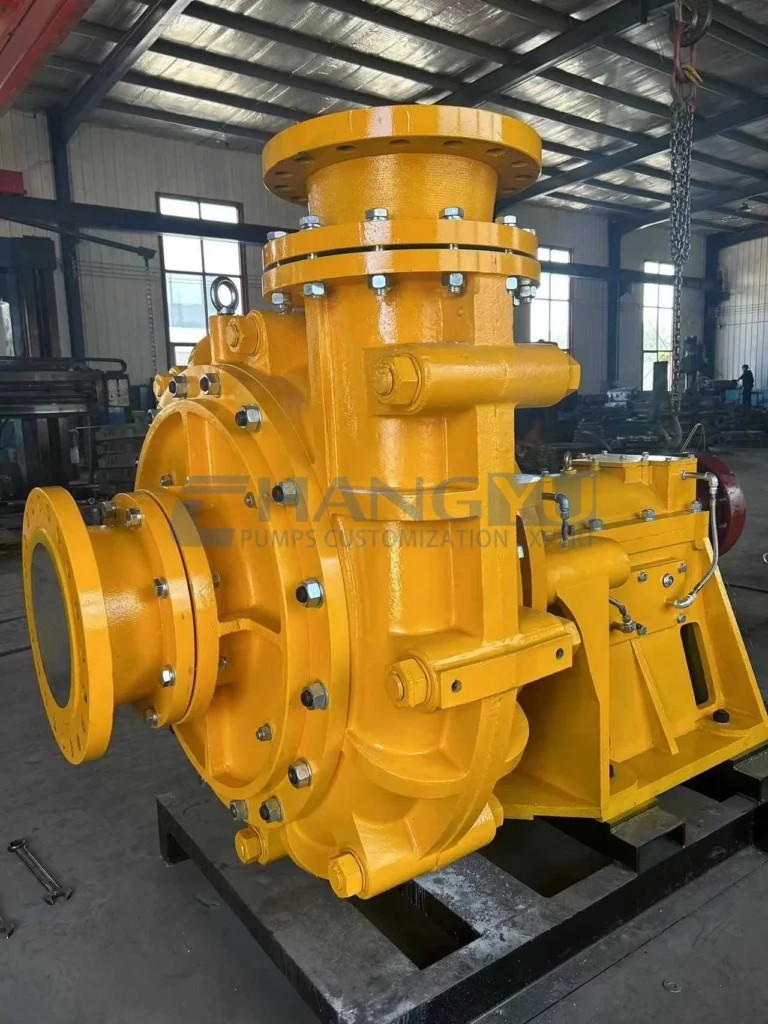
Dòng PGY — Bơm bùn cao áp hạng nặng cho dòng chảy hồi thủy lực
Được thiết kế cho điều kiện cao áp và mài mòn nghiêm trọng. Kết cấu vỏ kép cho phép thay thế các bộ phận tiếp xúc chất lỏng mà không cần tháo đường ống — một lợi thế quan trọng trên các giàn khoan chật hẹp. Cụm ổ trục bôi trơn bằng dầu đảm bảo độ tin cậy lâu dài trong vận hành tải nặng liên tục. Thiết kế cao áp (lên đến 101,6 m) cho phép chuyển trực tiếp từ đầu giếng đến bể thu gom tập trung mà không cần bơm tăng áp trung gian — giảm số lượng thiết bị và đơn giản hóa hậu cần giàn khoan.
| Tham số | Thông số kỹ thuật |
|---|---|
| Lưu lượng | 117–976 m³/h |
| Trưởng phòng | 21,1–101,6 m |
| Công suất động cơ | 22–560 kW |
| Tốc độ | 730 / 980 / 1.480 vòng/phút |
| Vật liệu | BTMCr27 / BTMCr28 / BTMCr33 / thép không gỉ duplex |
Dòng HB — Bơm thép không gỉ cho dòng chảy hồi ăn mòn
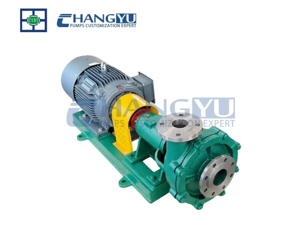
Bơm ly tâm ngang tuân thủ ISO 2858 với kết cấu tiếp xúc chất lỏng toàn thép không gỉ. Có sẵn trong 316L, duplex 2205 và super duplex 2507. Phù hợp cho dòng chảy hồi có phụ gia hóa chất, axit kích thích hồi lưu, hoặc nước sản xuất có hàm lượng clorua cao.
| Tham số | Thông số kỹ thuật |
|---|---|
| Lưu lượng | 10–60 m³/giờ |
| Trưởng phòng | 20–120 m |
| Công suất động cơ | 3–45 kW |
| Tốc độ | 2.900 vòng/phút |
| Nhiệt độ | -20°C đến 120°C |
| Vật liệu | 304 / 316L / 2205 / 2507 |
Dòng UHB — Bơm lót UHMW-PE cho dịch vụ dòng chảy hồi kinh tế
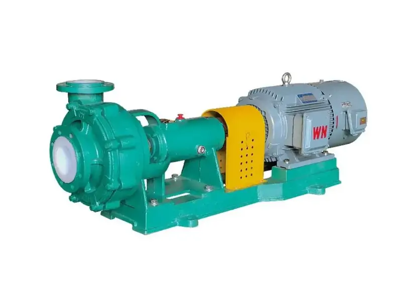
Bơm ly tâm lót UHMW-PE thép cho dòng chảy hồi cuối giai đoạn và nước sản xuất có hàm lượng cát vừa phải. UHMW-PE cung cấp khả năng chống ăn mòn kết hợp và chống mài mòn vượt trội với chi phí thấp hơn so với bơm toàn kim loại. Bánh công tác nửa hở xử lý các chất rắn còn lại.
| Tham số | Thông số kỹ thuật |
|---|---|
| Lưu lượng | 3–2.600 m³/giờ |
| Trưởng phòng | 5–100 m |
| Công suất động cơ | 0,75–300 kW |
| Tốc độ | 750–2.900 vòng/phút |
| Nhiệt độ | -20°C đến 90°C |
| Chất liệu lót | UHMW-PE |
Câu hỏi thường gặp về Bơm bùn dòng chảy hồi thủy lực
Hỏi: Vật liệu nào bền nhất trong dịch vụ bơm dòng chảy hồi thủy lực?
Đáp: Lớp lót cacbua vonfram và gốm (SiC) cung cấp tuổi thọ 6–12 tháng trong dòng chảy hồi tốc độ cao, nhiều cát, so với 3–4 tuần đối với Cr27 cao crom. Cacbua vonfram cung cấp khả năng chống va đập tốt hơn khi có các mảnh cắt góc cạnh; lớp lót gốm phù hợp nhất cho dòng chảy hồi hạt mịn với rủi ro va đập tối thiểu.
Hỏi: Tại sao bánh công tác bơm dòng chảy hồi của tôi mòn nhanh như vậy?
Đáp: Tốc độ mài mòn trong bơm dòng chảy hồi thủy lực tỷ lệ với lập phương của vận tốc dòng chảy — tăng gấp đôi vận tốc làm tăng mài mòn khoảng 8 lần. Nếu bơm của bạn đang hoạt động ở đầu trên của dải lưu lượng với nồng độ cát cao, nâng cấp lên lớp lót cacbua vonfram hoặc gốm là giải pháp hiệu quả nhất.
Hỏi: Làm thế nào để ngăn ngừa hỏng phớt bơm dòng chảy hồi?
Đáp: Đối với giàn khoan có nước sạch, lắp đặt xả ngoài API Plan 32 để ngăn cát tiếp cận bề mặt phớt. Đối với giàn khoan xa không có nước đáng tin cậy, phớt đẩy ly tâm với nhồi len loại bỏ hoàn toàn sự phụ thuộc vào nước bên ngoài. Đối với các vị trí nhạy cảm với môi trường, phớt kép API Plan 53C với giám sát áp suất chất lỏng chắn cung cấp mức bảo vệ rò rỉ cao nhất.
Hỏi: Tôi có thể sử dụng cùng một bơm cho dòng chảy hồi giai đoạn đầu và cuối không?
Đáp: Dòng chảy hồi giai đoạn đầu với đỉnh cát và khí yêu cầu bánh công tác xoáy và khả năng chống mài mòn tối đa. Dòng chảy hồi cuối giai đoạn với chất rắn vết cho phép bánh công tác nửa hở hiệu suất cao hơn. Sử dụng hai loại bơm — một dành riêng cho giai đoạn đầu, một cho dịch vụ liên tục — tối ưu hóa cả độ tin cậy và hiệu suất.
Hỏi: Tôi nên bảo quản bơm dòng chảy hồi giữa các giai đoạn thủy lực như thế nào?
Đáp: Xả bơm bằng nước sạch trước bất kỳ thời gian ngừng hoạt động nào vượt quá 48 giờ. Xoay trục hàng tuần để ngăn dính bề mặt phớt và phân phối lại chất bôi trơn ổ trục. Kiểm tra xoay trục tự do trước khi khởi động lại.
Hỏi: Lợi thế của thiết kế vỏ kép Dòng PGY cho dòng chảy hồi là gì?
Đáp: Thiết kế vỏ kép cho phép thay thế các bộ phận mài mòn tiếp xúc chất lỏng mà không cần ngắt kết nối đường ống hút và xả — một tiết kiệm thời gian đáng kể trên các giàn khoan chật hẹp nơi việc thay bơm khó khăn.
Danh sách kiểm tra phòng ngừa dành cho kỹ sư bơm Changyu
- Không chỉ định Cr27 cao crom cho dòng chảy hồi giai đoạn đầu với nồng độ cát và vận tốc cao. Cr33/Cr33M cao crom là tối thiểu; cacbua vonfram cung cấp khả năng chống va đập tốt nhất cho điều kiện cát đỉnh.
- Tính toán vận tốc dòng chảy thực tế trong bơm — không chỉ vận tốc đường ống. Tốc độ mài mòn tăng với lập phương của vận tốc. Chọn bơm quá khổ để “an toàn” thực tế làm tăng tốc mài mòn bằng cách tăng vận tốc bên trong.
- Đối với giàn khoan xa không có nước sạch đáng tin cậy, chỉ định phớt đẩy ly tâm với nhồi len. Không phụ thuộc vào xe chở nước để xả phớt — một lần giao hàng bị bỏ lỡ gây ra hỏng phớt thảm khốc.
- Lắp đặt điều khiển VFD cho khả năng khởi động mềm và khớp lưu lượng. Khởi động trực tiếp với cát lắng trong vỏ bơm gây sốc cơ học quá mức. Cấu hình tăng tốc 15–30 giây cho bơm lớn (>100 kW); 5–10 giây cho bơm nhỏ hơn.
- Thực hiện quy trình xả nước ngọt trước bất kỳ thời gian ngừng hoạt động nào vượt quá 48 giờ. Cát và hóa chất còn lại trong vỏ bơm gây ăn mòn và vấn đề khởi động lại.
- Xoay trục bơm hàng tuần trong thời gian ngừng hoạt động kéo dài. Điều này ngăn ngừa dính bề mặt phớt — một nguyên nhân phổ biến gây hỏng khởi động lại.
- Đối với giàn khoan nhiều giếng, tiêu chuẩn hóa hai loại bơm: một cho dòng chảy hồi giai đoạn đầu (lót cacbua vonfram, bánh công tác xoáy, phớt đẩy ly tâm) và một cho nước sản xuất liên tục (Cr33 cao crom, bánh công tác nửa hở, hiệu suất cao hơn).
- Đối với lắp đặt API Plan 53C, lắp đặt đồng hồ áp suất và báo động áp suất thấp trên bình chứa chất lỏng chắn. Mất áp suất chắn có nghĩa là phớt trong đang rò rỉ và bơm nên được tháo ra để thay phớt trước khi phớt ngoài hỏng.
Kết luận
Bơm bùn dòng chảy hồi thủy lực là một bơm được chỉ định mục đích cho một trong những ứng dụng mài mòn nhất và vận hành khắt khe nhất trong ngành dầu khí. Ba yếu tố quyết định độ tin cậy của bơm và thời gian hoạt động hiệu quả: lựa chọn vật liệu phù hợp với nồng độ cát và vận tốc dòng chảy, thiết kế bánh công tác xử lý cả chất rắn và khí cuốn theo, và bảo vệ phớt hoạt động đáng tin cậy trong điều kiện giàn khoan xa.
Đối với giai đoạn đầu của dòng chảy hồi với nồng độ cát đỉnh, lớp lót cacbua vonfram mang lại khả năng chống va đập và tuổi thọ mài mòn mà hợp kim crom cao tiêu chuẩn không thể sánh kịp. Phớt ly tâm dạng đẩy loại bỏ sự phụ thuộc vào nước xả khiến các phớt cơ khí thông thường không đáng tin cậy trên các giàn khoan xa. Quy trình xả nước ngọt và xoay trục hàng tuần trong thời gian ngừng hoạt động ngăn ngừa ăn mòn và kẹt phớt gây ra sự cố khi khởi động lại.
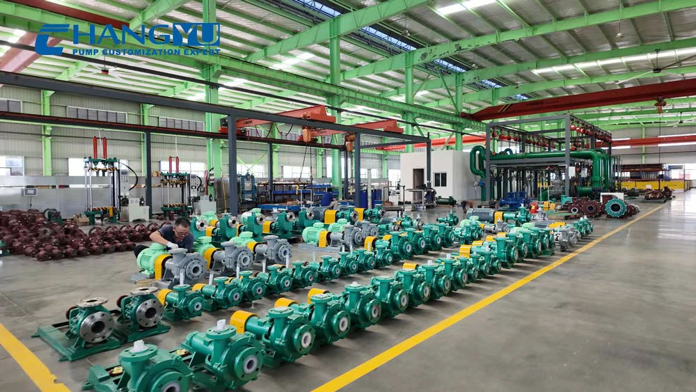
Khi bạn sẵn sàng chỉ định một máy bơm dòng chảy hồi cho hoạt động bẻ gãy thủy lực của mình, đội ngũ kỹ thuật của Changyu Pump có thể cung cấp đánh giá kỹ thuật bao gồm phân loại cát, khuyến nghị vật liệu và cấu hình phớt phù hợp với điều kiện giàn khoan cụ thể của bạn. Hai thập kỷ sản xuất máy bơm chống mài mòn trong các ứng dụng khai thác mỏ, hóa chất và mỏ dầu là cơ sở cho mọi khuyến nghị.