
Most boiler feed pumps that fail early were not badly built. They were sized with a number that was never quite the right number — evaporation taken as flow, gauge pressure taken as head, and a suction condition assumed to be “fine” because the deaerator looked generous on the drawing.
A boiler feed pump calculation comes down to four quantities: flow, head, shaft power, and NPSH available at the pump suction. Get those four right and the pump selection is straightforward. Get any one of them wrong, and the error usually shows up months later as cavitation damage, a throttled control valve, or a motor running near its service factor.
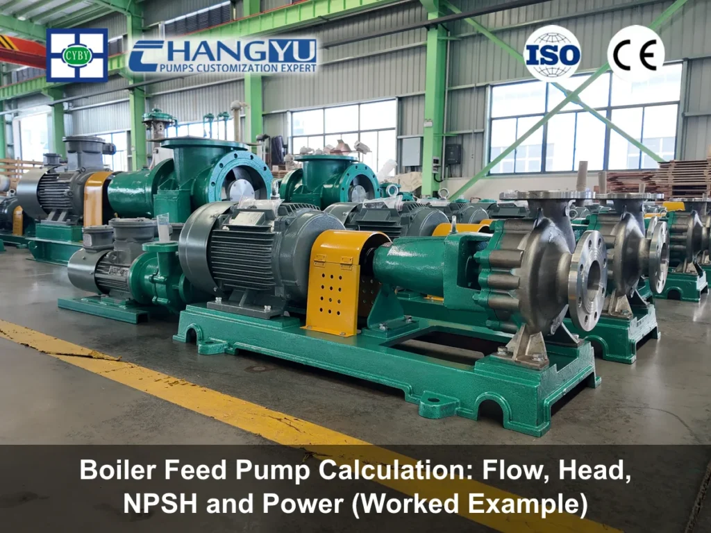
This is the method we use at Changyu Pump when a plant engineer sends us a duty point. It takes about fifteen minutes with a calculator, and it will tell you more about the pump you need than a page of catalogue curves.
The four inputs, before any formula: evaporation rate (t/h or kg/s), boiler drum pressure (MPa g), feedwater temperature at the pump suction (°C), and deaerator elevation above the pump centreline (m). Everything below is derived from those.
The boiler feed pump calculation in four steps
The sequence matters. Flow sets the operating point on the curve. Head sets which curve. Power tells you the motor and the operating cost. NPSH decides whether the pump can run at that point at all — and it is the step most often skipped, because it is the only one that gets harder as the water gets hotter.
| Étape | Quantity | Formule | What it protects against |
|---|---|---|---|
| 1 | Rated flow | (evaporation + blowdown) × (1 + margin) | Running dry, poor level control |
| 2 | Rated head | Δp between drum and deaerator ÷ ρg + losses + margin | Starved boiler at low drum pressure |
| 3 | Puissance de l'arbre | P = ρgQH / (3.6×10⁶ × η) | Undersized motor, overload trips |
| 4 | NPSH available | (p_deaerator + ρgH_s − Δp_suction − p_vapour) / ρg | Cavitation, impeller erosion |
Step 1: Flow — evaporation plus blowdown plus margin
Feedwater flow is not the boiler’s steam rating. It is the steam rating, plus whatever leaves the drum as blowdown, plus a design margin you can defend.
Blowdown is set by your water treatment programme and the boiler manufacturer’s limits on total dissolved solids, alkalinity and silica. For a packaged industrial boiler on good make-up water it commonly sits between 1 % and 5 % of evaporation; boilers on high make-up or poor-quality feed can run considerably higher. Using 2 % because “that’s typical” without checking the boiler data sheet is how plants end up short of water at full firing.
The margin covers level-control swing and modest load excursions. Five to ten per cent is the usual range, and it should be applied once — to the final duty point, not compounded onto every line item.
Worked numbers: a 10 t/h boiler at 2% blowdown with a 5% margin.
Evaporation: 10,000 kg/h
Blowdown: 10,000 × 0.02 = 200 kg/h
Subtotal: 10,200 kg/h
At 954 kg/m³ (water at 105 °C): 10.69 m³/h
Rated flow: 10.69 × 1.05 = 11.2 m³/h
Step 2: Head — drum pressure plus losses plus margin
Total head is the pressure difference the pump has to overcome, expressed in metres of the water actually being pumped, plus system losses.
Start with the pressure differential between the steam drum and the deaerator — both in absolute pressure, not gauge. That difference already contains the elevation from deaerator to drum, so you do not add static height twice.
Then work in metres of head using the density at the pump’s temperature. For 105 °C feedwater that is about 954 kg/m³. If you use 1,000 kg/m³ out of habit, you will understate head by roughly 4.6 % — small, but it stacks with every other small error.
Add the losses: economiser and feed line friction, plus the pressure drop across the feed control valve. That valve drop deserves real attention. The pump sees its lowest system resistance at low boiler load, and the control valve has to absorb the difference. A valve sized for 20–30 m of drop at maximum continuous rating gives the control loop room to work; a valve sized for 5 m will be wide open at full load and hunting at part load.
Worked numbers:
- Drum: 1.6 MPa g = 1,701 kPa a. Deaerator: 125 kPa a. Δp = 1,576 kPa
- Static component: 1,576,000 ÷ (954 × 9.81) = 168.4 m
- Economiser and feed line friction: 25 m
- Feed control valve drop at MCR: 25 m
- Elevation from pump to drum: 8 m
- Design head: 226.4 m
- Rated head with 5 % margin: 238 m
Step 3: Shaft power — the number your electricity bill reads
Shaft power follows directly from flow, head and density:
P (kW) = ρ × g × Q × H ÷ (3.6 × 10⁶ × η)
with ρ in kg/m³, Q in m³/h, H in m, and η the pump efficiency at that duty point — taken from the tested curve, not assumed. A small multistage pump at 11 m³/h typically lands in the 60–70 % region; we use 68 % here.
P = 954 × 9.81 × 11.2 × 238 ÷ (3.6 × 10⁶ × 0.68) = 10.2 kW
Motor selection is a separate decision from shaft power. The next standard rating above 10.2 kW is 11 kW, which leaves almost nothing for cold starting — and cold feedwater is roughly 4 % denser than water at 105 °C, so the pump draws more power before the deaerator is up to temperature. In practice we specify 15 kW here and accept the small efficiency penalty. Two ratings of headroom on a continuously running machine is cheap insurance; a motor running at 95 % load for years is not.
For operating cost, multiply shaft power by running hours and your tariff, then divide by motor efficiency. On a 24/7 boiler that 10.2 kW becomes roughly 89 MWh a year — which is why a few points of pump efficiency are worth arguing about during selection, and why operating far left of best efficiency point is expensive even when nothing appears to be broken.
Step 4: NPSH at 105 °C — where most feed pump calculations go wrong
This is the step that separates a feed pump from a water transfer pump, and the one worth reading twice.
NPSH available at the pump suction:
NPSHa = (p_deaerator + ρgH_s − Δp_suction − p_vapour) ÷ ρg
with p_deaerator in kPa absolute, H_s the minimum liquid level above the pump centreline in metres, Δp_suction the suction line loss in kPa, and p_vapour the vapour pressure of water at the maximum feed temperature.
Here is the part that catches people. At 105 °C, the vapour pressure of water is 120.8 kPa absolute — and a deaerator operating at 105 °C sits at roughly 125 kPa absolute. The two numbers are almost the same, by definition: the deaerator is holding water at its saturation temperature. That leaves about 4 kPa of pressure margin, which is less than half a metre of head.
So NPSHa at 105 °C is not really a pressure calculation at all. It is an elevation calculation. Whatever height you put between the deaerator and the pump, minus what you lose in the suction pipe, is essentially the whole of your available NPSH.
Worked numbers: deaerator 7 m above pump centreline, 0.6 m of suction line loss.
- Deaerator pressure: 125 kPa
- Static: 954 × 9.81 × 7 ÷ 1000 = 65.5 kPa
- Suction loss: 954 × 9.81 × 0.6 ÷ 1000 = 5.6 kPa
- Vapour pressure at 105 °C: 120.8 kPa
- NPSHa = (125 + 65.5 − 5.6 − 120.8) ÷ (954 × 9.81 ÷ 1000) = 7.1 m
Against a first-stage NPSHr of 3.5 m, that is a margin of 3.6 m — healthy. Now drop the deaerator to 5 m and let the suction line loss rise to 1.5 m because the pipe was sized on velocity rather than NPSH:
NPSHa = (125 + 46.8 − 14.0 − 120.8) ÷ 9.36 = 4.0 m
Margin over 3.5 m NPSHr: 0.5 m
Half a metre is not a margin. That pump will cavitate on a hot afternoon, and the damage will appear on the first-stage impeller long before anyone connects it to the deaerator height. The fix is rarely exotic: raise the deaerator, enlarge the suction line, or specify a low-NPSH first-stage impeller. All three are cheap at design stage and expensive afterwards.
A rule we apply: target at least 1.5 m of NPSH margin at maximum feed temperature, and never accept a margin below 1 m without a written hydraulic review. For deaerators below 100 °C the pressure cushion is wider and the calculation is more forgiving — but do not carry a 60 °C assumption into a 105 °C design.
The complete worked example, in one table
A 10 t/h saturated steam boiler, 1.6 MPa g, 2 % blowdown, 5 % design margin, 105 °C deaerator water 7 m above the pump.
| Objet | Valeur | Basis |
|---|---|---|
| Evaporation | 10,000 kg/h | Boiler rating |
| Blowdown | 200 kg/h | 2 % of evaporation |
| Débit nominal | 10.69 m³/h | 10,200 kg/h ÷ 954 kg/m³ |
| Rated flow | 11.2 m³/h | +5 % margin |
| Drum / deaerator Δp | 1,576 kPa | 1,701 − 125 kPa a |
| Static head component | 168.4 m | Δp ÷ ρg at 954 kg/m³ |
| Friction + control valve + lift | 58 m | 25 + 25 + 8 |
| Hauteur manométrique nominale | 226.4 m | Sum |
| Rated head | 238 m | +5 % margin |
| Pump efficiency at duty | 68 % | Tested curve |
| Puissance de l'arbre | 10.2 kW | ρgQH ÷ 3.6×10⁶η |
| Motor selected | 15 kW | Cold-start headroom |
| NPSHa | 7.1 m | Deaerator 7 m above pump |
| NPSHr (first stage) | 3.5 m | Pump data |
| NPSH margin | 3.6 m | Acceptable |
The duty point to put on the enquiry is 11.2 m³/h at 238 m, 105 °C, NPSHa 7.1 m, 15 kW. That is a complete specification. A supplier given those five numbers cannot misunderstand you.
Five sizing errors we see repeatedly
Compounding margins. Five per cent on flow, then another five on head, then a 10 % “engineering allowance” on top produces a pump 20 % oversized. It will run left of its preferred operating range, its control valve will throttle away the excess, and the efficiency you paid for disappears. Apply margin once.
Treating blowdown as negligible. Two per cent is a default, not a measurement. Check the boiler data sheet against your actual water chemistry.
Sizing head at design drum pressure only. The pump must still deliver at the lowest drum pressure the boiler will see at full firing, which is the worst case for head. Size for that.
Assuming NPSH is generous because the deaerator is large. Tank volume has nothing to do with NPSH. Height above the pump centreline and suction line loss do.
Ignoring cold-start power. Cold water is denser. If the pump starts before the deaerator is at temperature, it draws more power than the duty calculation shows.
Boiler feed pump calculation, then pump selection
The four steps above give you a duty point. Turning that into a pump is where configuration matters, and it is worth being precise about one thing: a 105 °C feedwater duty sits above the standard temperature limit of many general-purpose multistage ranges, which are commonly built for media up to 80 °C. Boiler feed service needs a high-temperature build — different sealing, different clearances, and a confirmed NPSHr.
At Changyu Pump we build the multistage configurations that feed pump duties draw on: the MD Series high pressure multistage pump covers 3.75–850 m³/h and heads to 816 m, the pompe centrifuge horizontale multicellulaire extends motor power to 1,600 kW, and the pompe centrifuge multicellulaire verticale handles smaller flows where floor space is tight. For lower-head feed and condensate transfer, the CYH centrifugal pump is the sensible starting point.
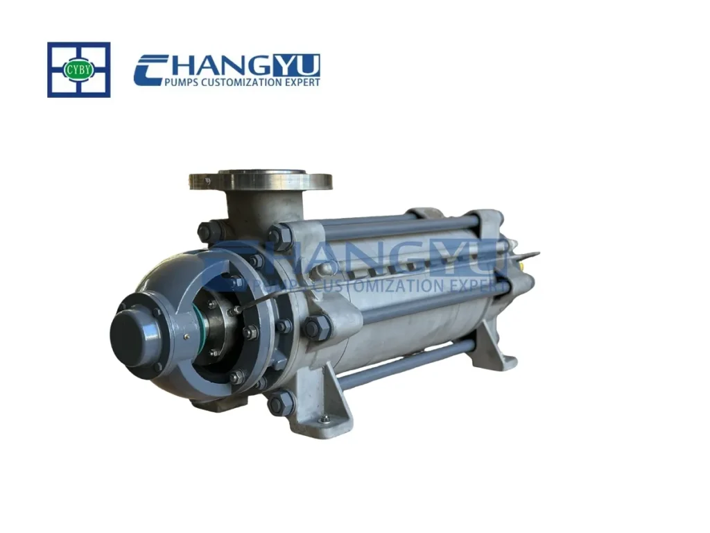
Pompe multicellulaire haute pression de la série MD
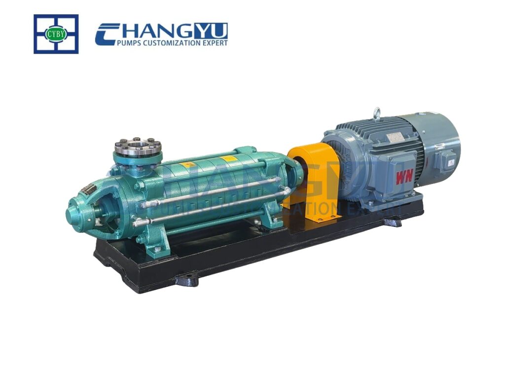
Pompe centrifuge multicellulaire horizontale résistante à la corrosion de la série DF
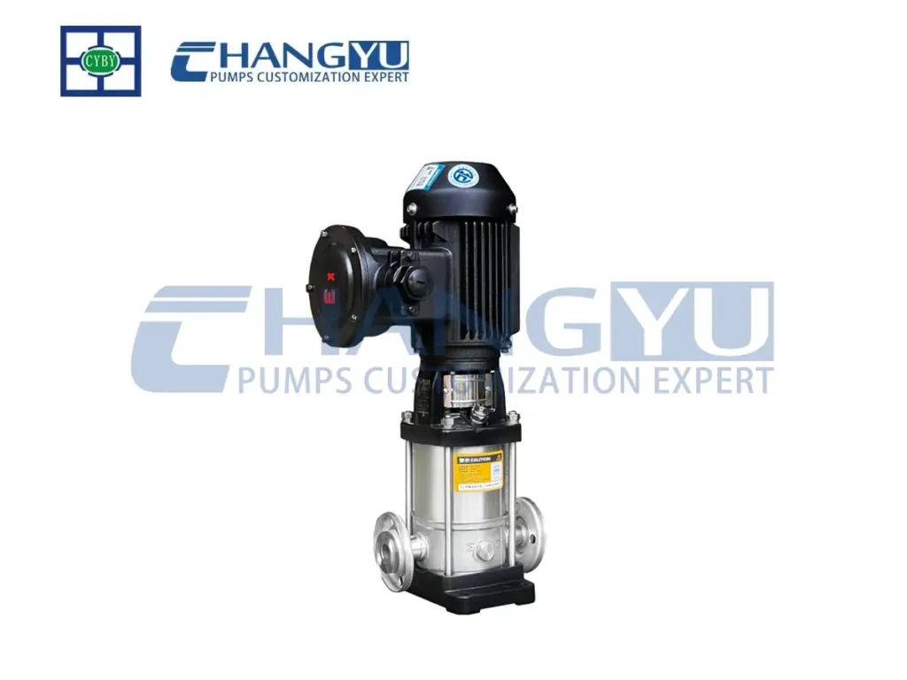
Pompe centrifuge multicellulaire verticale de la série CDL
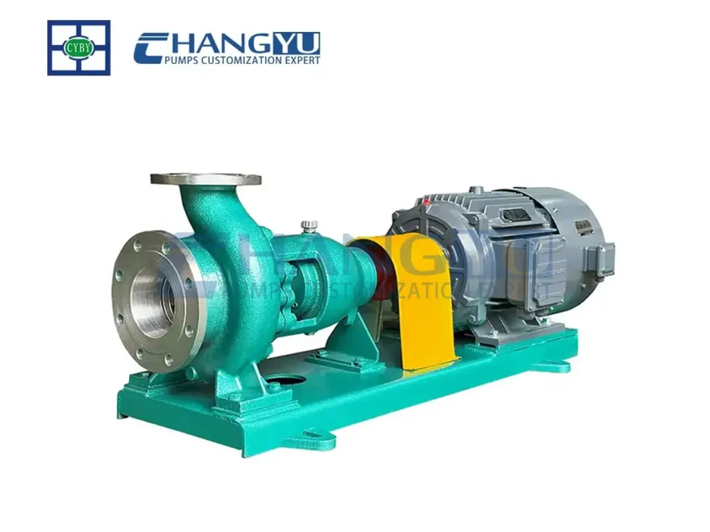
Pompe centrifuge en acier inoxydable pour produits chimiques de la série CYH
Send us the duty point and we will confirm the temperature build, the first-stage NPSHr and the tested curve before quoting — because the number that matters is not the one on the catalogue page, it is the one your deaerator will actually deliver.
If you have any further questions, please contact us.
Courriel : [email protected]
TÉL/WA : +86-13651913727
Inside our factory
Anhui Changyu Pump and Valve Manufacturing Co., Ltd. has been building industrial pumps since 2006, from a 20,000 m² facility in the Yangtze River Delta manufacturing base in Jingxian, Xuancheng, Anhui. Around 100 employees produce more than 20,000 units a year across 14 series and over 100 product variants, with 21 years of OEM and ODM experience behind the custom work.
The plant runs its own pump test bench and water pump test system, so every unit is performance-tested before it ships — which is how we can quote a curve rather than an estimate. We hold ISO 9001, CE and ATEX certification, and we cast and machine in cast iron, ductile iron, wear-resistant alloys, stainless steels including 316/316L/2205/2507, and titanium. Our pumps run in the United States, Europe, South Africa and Southeast Asia.
FAQ
Q: How do I calculate the flow rate for a boiler feed pump?
A : Take the boiler’s evaporation rate, add blowdown (typically 1–5 % of evaporation, set by your water treatment limits), convert to volumetric flow at the feedwater density, then add a single design margin of 5–10 %. A 10 t/h boiler with 2 % blowdown and 5 % margin needs about 11.2 m³/h at 105 °C.
Q: What head does a boiler feed pump need?
A : The pressure difference between the steam drum and the deaerator, converted to metres of head at the feedwater density, plus economiser and piping friction, feed control valve drop, and elevation. For a 1.6 MPa g drum with a 125 kPa deaerator, the pressure component alone is about 168 m; total design head typically lands near 225–240 m.
Q: Why is NPSH so critical at 105 °C?
A : Because 105 °C is the saturation temperature at roughly 120 kPa, and a deaerator runs at almost exactly that pressure. The pressure margin above vapour pressure is nearly zero, so NPSHa is determined almost entirely by how far the deaerator sits above the pump and how much you lose in the suction line.
Q: How much NPSH margin should I allow?
A : At least 1.5 m at maximum feed temperature is our working rule, and never below 1 m without a hydraulic review. Below that, normal variation in deaerator level and suction strainer fouling is enough to cause cavitation.
Q: Can a standard multistage pump handle 105 °C feedwater?
A : Not usually as catalogued. Many general-purpose multistage ranges are rated to 80 °C. A 105 °C duty needs a high-temperature configuration with the seal, clearances and NPSHr confirmed for the actual temperature.
Q: How do I calculate the motor size for a feed pump?
A : Calculate shaft power from P = ρgQH ÷ (3.6×10⁶η), then select one or two standard motor ratings above it to cover cold starting and density variation. For 10.2 kW of shaft power, a 15 kW motor is the practical choice.
Q: Fixed speed or variable speed for a boiler feed pump?
A : It depends on load profile. A boiler running steady at high load is well served by a fixed-speed pump with a recirculation line; a plant with wide, frequent load swings usually recovers the VFD cost through reduced throttling loss. The calculation above gives the duty point either way.
Talk to us about your duty point
Send the evaporation rate, drum pressure, feedwater temperature and deaerator height, and we will return a sized duty point, a temperature-appropriate configuration and a tested curve. Most enquiries are answered within 24 hours.
Courriel : [email protected]
TÉL/WA : +86-13651913727
Prefer to start with the selection questions rather than the arithmetic? Our boiler feed water pump selection checklist covers materials, seals and controls; the centrifugal pump range shows the configurations those answers lead to.
Summing up
Boiler feed pump calculation is four numbers in a fixed order: flow from evaporation plus blowdown plus one margin, head from the drum-to-deaerator pressure difference plus losses plus one margin, power from flow and head at the tested efficiency, and NPSH from deaerator elevation minus suction loss at the real feed temperature. The first three decide what you buy. The fourth decides whether it survives.