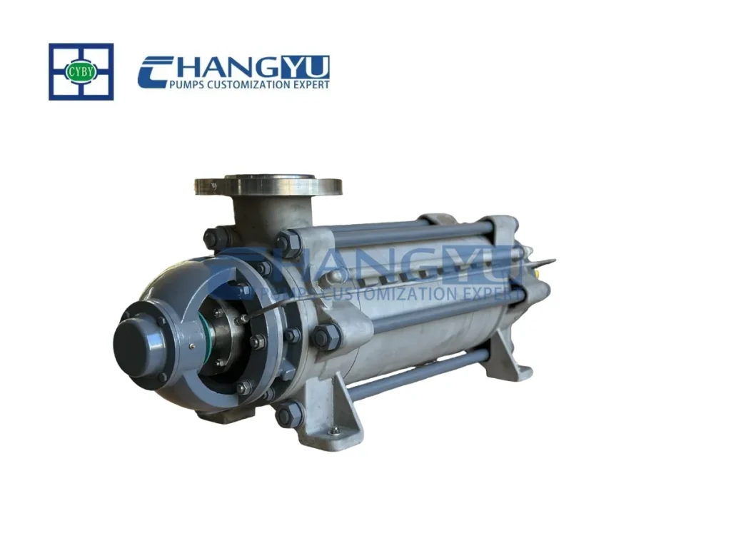

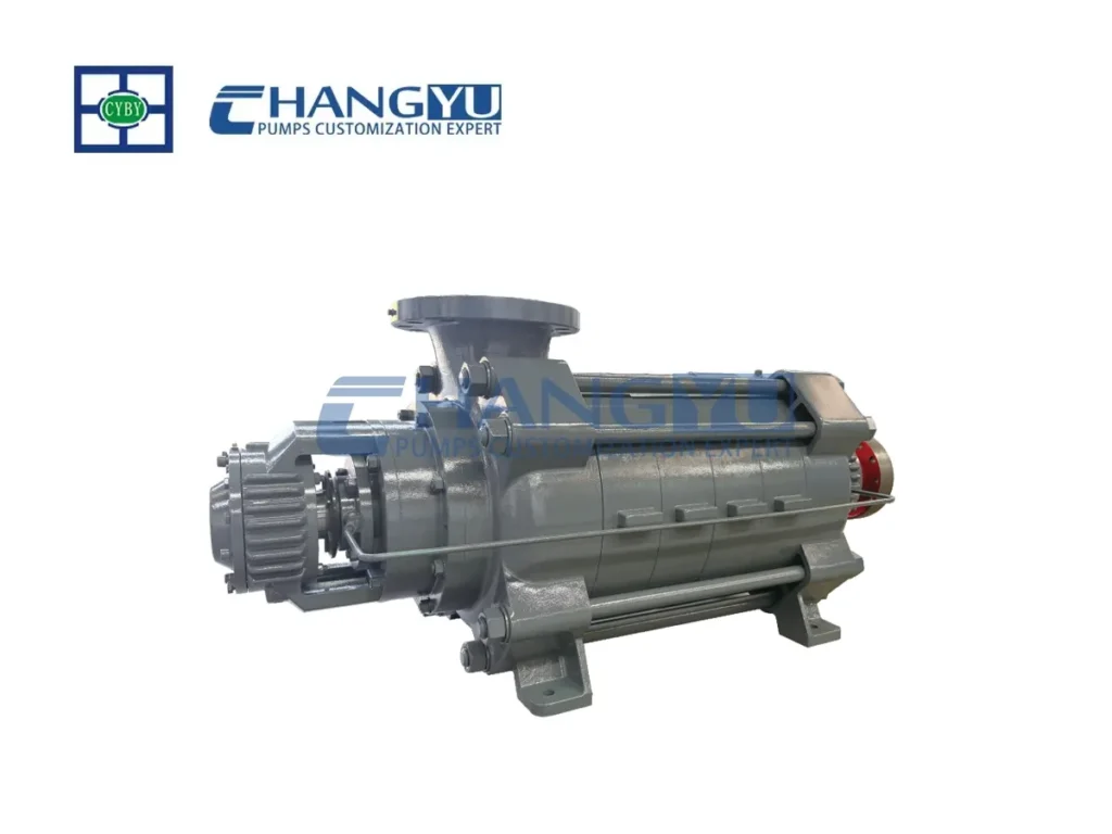

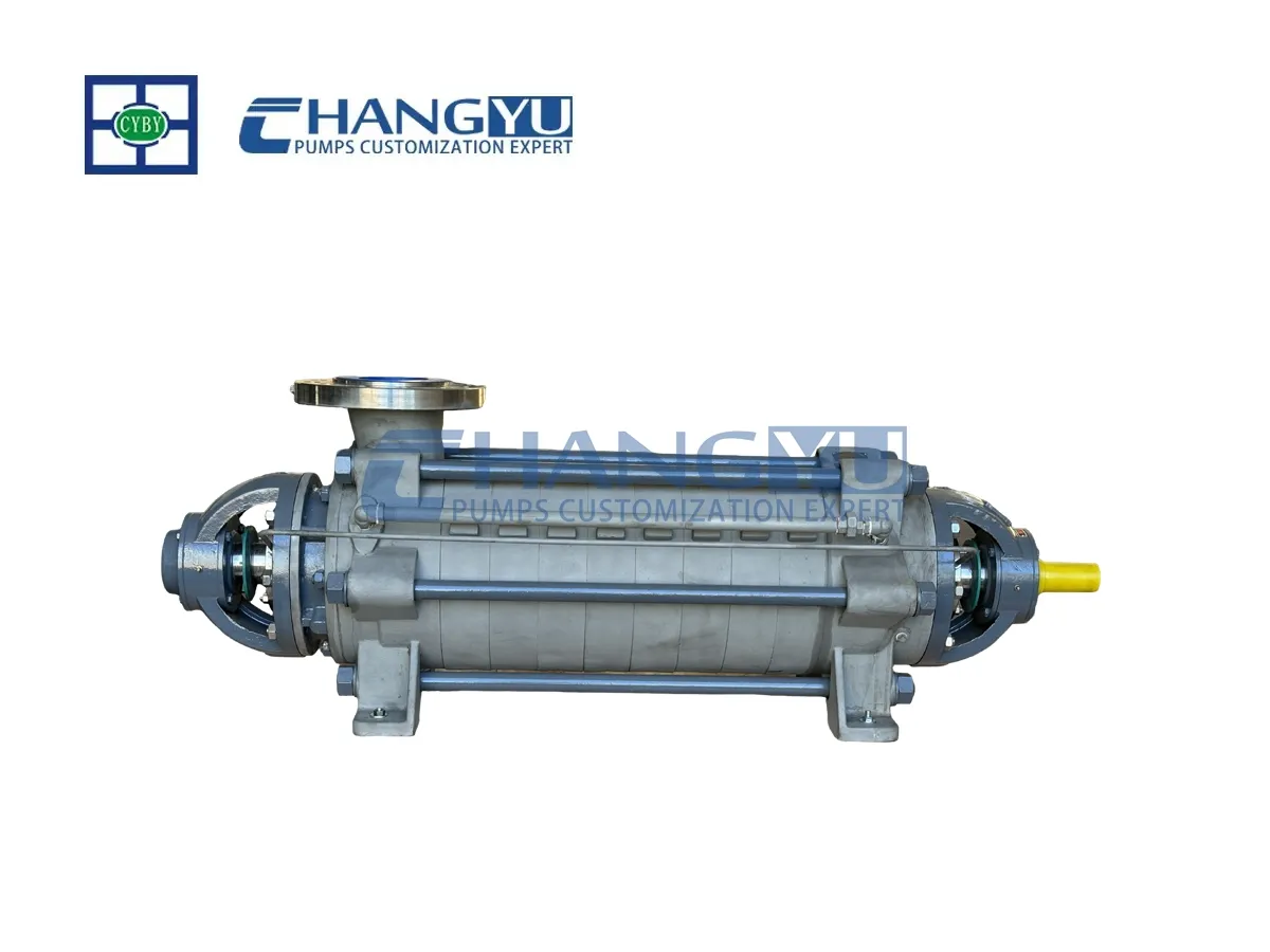


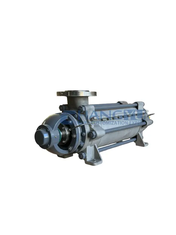
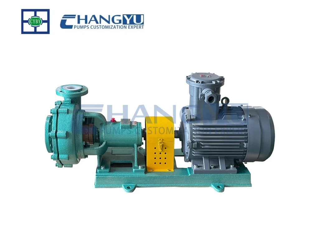
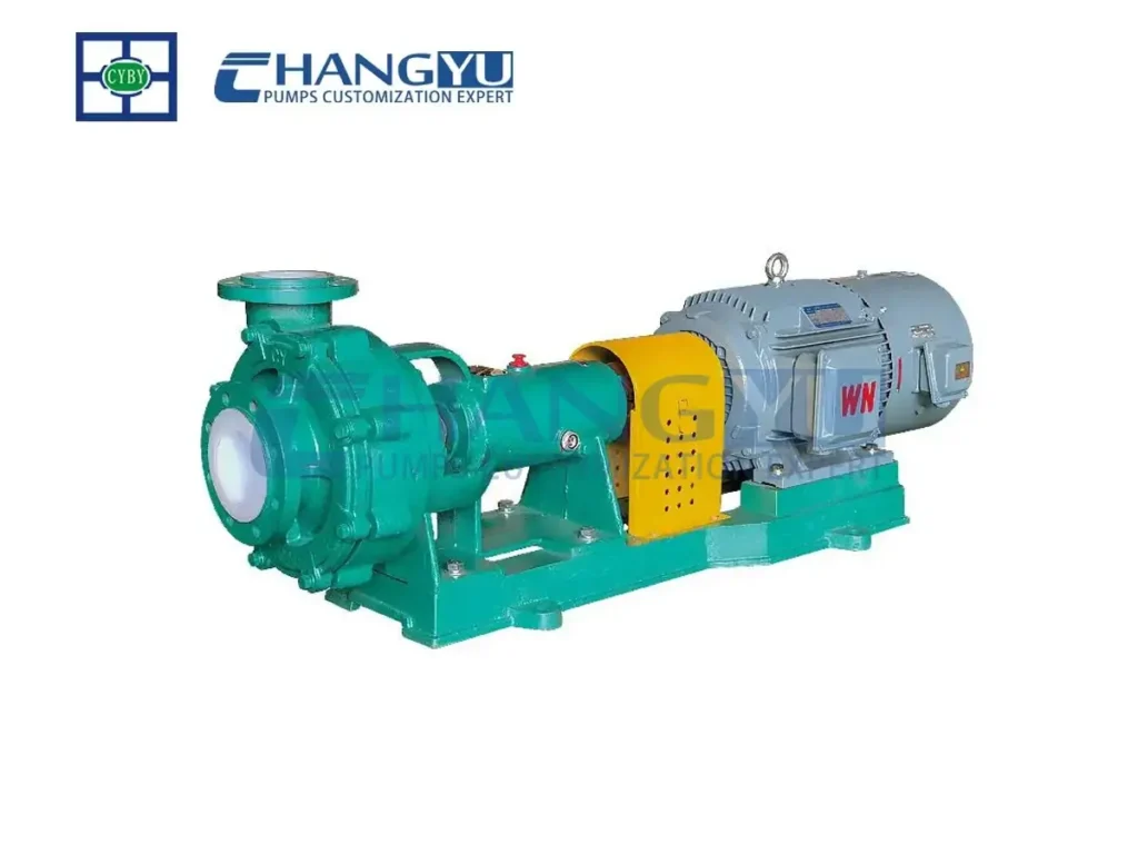
مضخة متعددة المراحل عالية الضغط من سلسلة MD
المضخة متعددة المراحل عالية الضغط من سلسلة MD هي نوع من مضخات الطرد المركزي المجزأة متعددة المراحل تتميز بدفاعتين أو أكثر مثبتتين على العمود. يتصل منفذ التفريغ للمرحلة الأولى بمدخل المرحلة الثانية، بينما يتصل منفذ التفريغ للمرحلة الثانية بمدخل المرحلة الثالثة. هذا التكوين المتصل على التوالي يشكل مضخة طرد مركزي متعددة المراحل.
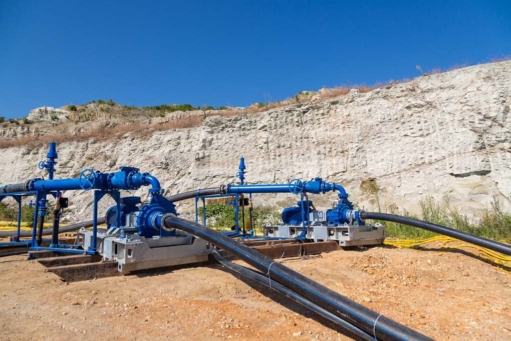
مناسبة لنقل المياه الجوفية من عمليات التعدين أو مياه الصرف الصحي البلدية التي تحتوي على جسيمات صلبة بتركيز ≤1.5%، وقطر جسيمات ≤0.5 مم، ودرجة حرارة أقل من 80 درجة مئوية.
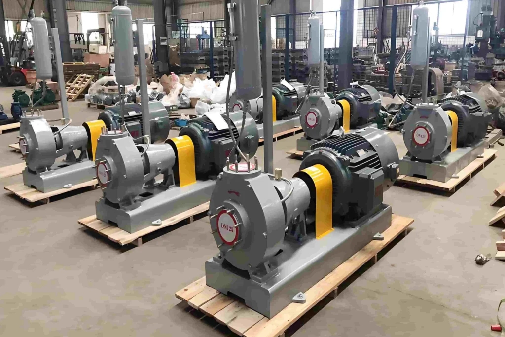
مضخات تشانغيو يدعم إنتاجك المخصص.
|
نطاق معدل التدفق : |
3.75 م³/ساعة ~ 850 م³/ساعة |
|---|---|
|
نطاق الرأس: |
19 م ~ 816 م |
|
قوة المحرك : |
7.5 كيلو وات ~ 450 كيلو وات |
|
السرعة: |
2980 ~ 1480 لفة/دقيقة |
|
نطاق درجة الحرارة المتوسطة: |
80°C |
|
مواد قابلة للتخصيص: |
الحديد الزهر، وحديد الدكتايل، وسبائك الصلب المقاوم للتآكل، وسبائك الحديد الزهر المقاوم للتآكل، والفولاذ المقاوم للحرارة، ودرجات مختلفة من الفولاذ المقاوم للصدأ، وسبائك التيتانيوم، والسيراميك، إلخ. |
مقدمة
المضخة متعددة المراحل عالية الضغط من سلسلة MD عبارة عن مضخة أفقية أحادية الشفط ومتعددة المراحل ذات هيكل أسطواني مجزأ متعدد المراحل مضخة طرد مركزي. وهو يستخدم النموذج الهيدروليكي الأكثر تقدماً وموثوقية المتاح حالياً ويستخدم عادةً في مشاريع هندسة الأنفاق والتعدين وحفر الأنفاق.
بالنسبة لموازنة القوة المحورية، تستخدم مضخات Changyu نظام موازنة متقدم من أربع مراحل يتميز بهيكل أسطواني حلقي مثبت، والذي تم التحقق من صحته من خلال أكثر من عقد من التطبيق العملي. وبالاقتران مع تقنية تحديد موضع الخلوص المحوري الدقيق، يحقق هذا النظام التوازن الكامل للقوة المحورية، مما يضمن التشغيل المستقر والموثوق.
كما تقدم المضخة متعددة المراحل عالية الضغط من سلسلة MD مزايا مثل نطاق الكفاءة العالية الواسع، ودورة اضمحلال الكفاءة الممتدة، وطيف الأداء الواسع، والتشغيل السلس، والتشغيل السلس، والضوضاء المنخفضة، وعمر الخدمة الطويل، والتركيب والصيانة المريحين. إنها تلبي المتطلبات المزدوجة للكفاءة العالية وتوفير الطاقة والمتانة المستقرة في مختلف التطبيقات الصناعية.
واعتمادًا على الوسيط المنقول، يمكن تخصيص المنتج بمواد مطابقة لضمان التشغيل الآمن والموثوق حتى في ظل الظروف القاسية التي تنطوي على التآكل والتآكل.
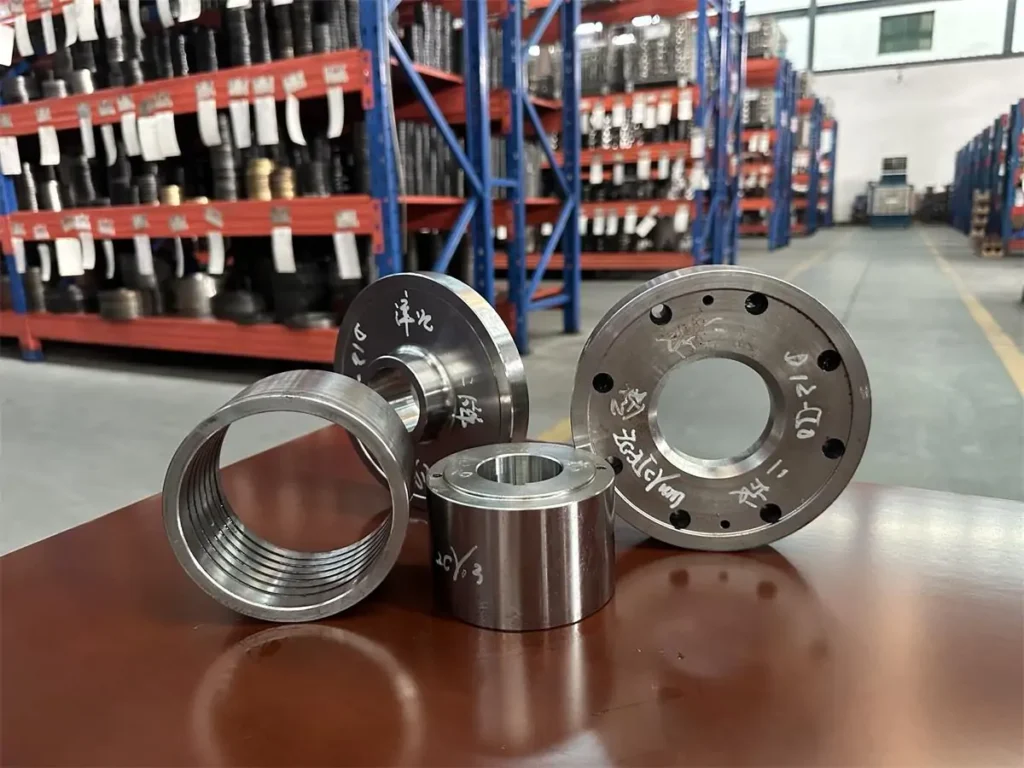
أجزاء المضخة متعددة المراحل ذات الضغط العالي
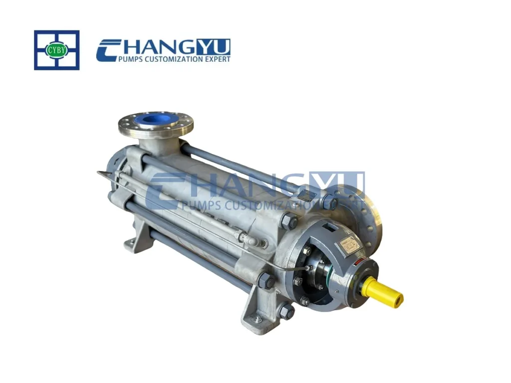
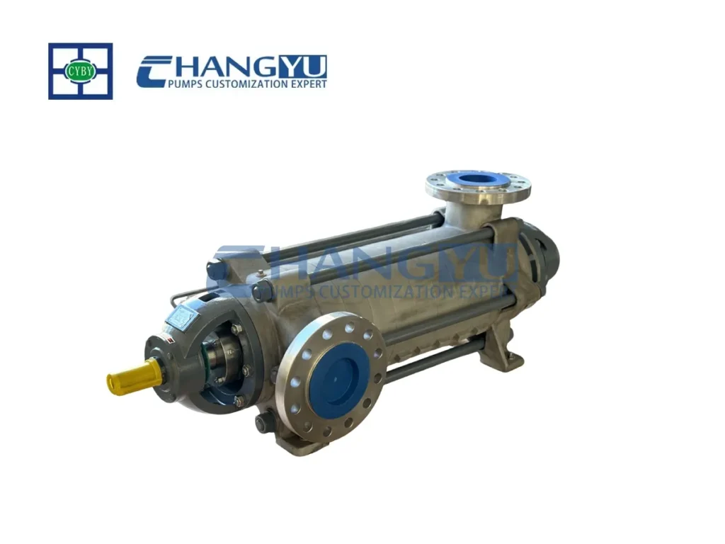
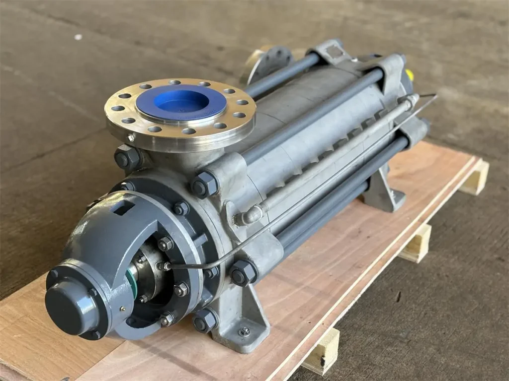
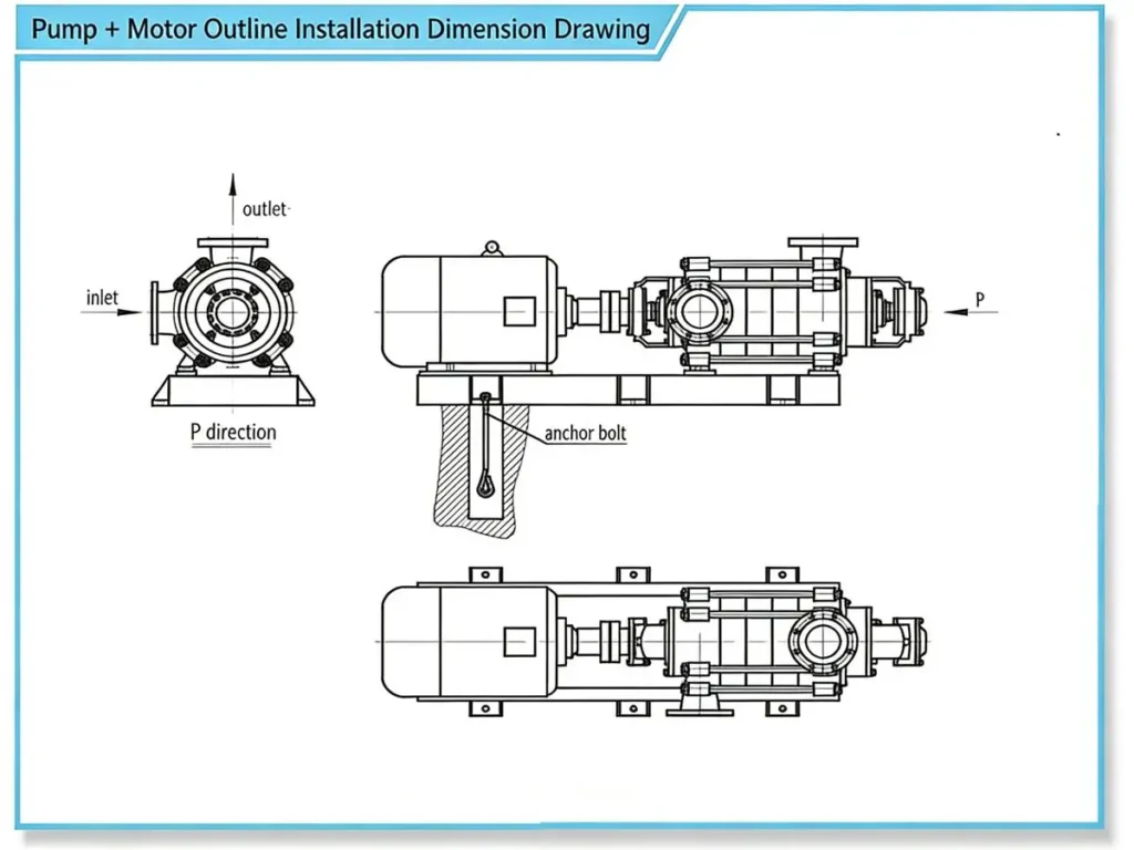
المضخة الصناعية MD عبارة عن مضخة طرد مركزي أفقية أحادية الشفط مجزأة متعددة المراحل. مدخل الشفط أفقي، بينما مخرج التفريغ عمودي لأعلى. يتم تجميع أقسام غلاف المضخة - بما في ذلك قسم المدخل، والقسم الوسيط، وقسم التفريغ - في وحدة واحدة عن طريق براغي شد. يتم تركيب مجموعات المحامل في كلا الطرفين، ويتم تحديد عدد المراحل بناءً على الرأس المطلوب للمضخة.
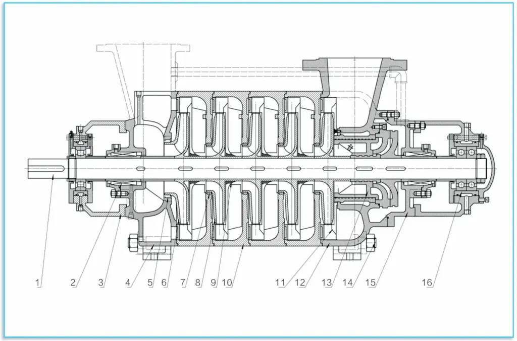
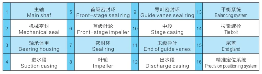
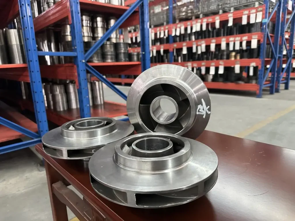
تتكون مجموعة الدوار بشكل أساسي من العمود والمكونات المركبة عليه، بما في ذلك الدفاعات وأكمام العمود ونظام الموازنة. يتوافق عدد الدفاعات مع عدد مراحل المضخة. يتم تثبيت الأجزاء المثبتة على العمود على العمود باستخدام مفاتيح مسطحة وصواميل العمود. يتم دعم الدوار بأكمله بواسطة محمل أسطواني واحد في طرف المحرك ومحملين كرويين في الطرف غير الدافع. إذا تم استخدام محمل العمود المنزلق، يلزم أيضًا دعامة تحديد الموضع بدقة في الطرف غير الدافع. يتطلب المحمل المنزلق في الطرف غير الدافع دعامة إضافية لتحديد الموضع بدقة. المحامل لا تتحمل القوى المحورية؛ نظام موازنة من نوع الأسطوانة يوازن القوى المحورية غير المتوازنة.
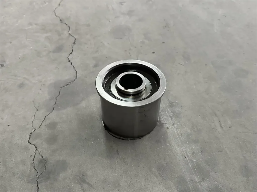
تستخدم الأسطح المانعة للتسرب بين قسم مدخل المضخة والقسم الوسيط وقسم المخرج مانع التسرب أو مانعات التسرب الحلزونية. يتم تركيب حلقات منع التسرب وأكمام ريشة التوجيه بين مجموعة الدوار والمكونات الثابتة. استبدل حلقات منع التسرب وأكمام ريشة التوجيه على الفور عندما يؤثر تآكلها على أداء المضخة. عندما يؤثر تآكل حلقات منع التسرب أو أكمام الريشة الموجهة على أداء المضخة، يجب استبدالها على الفور. تشمل خيارات ختم العمود موانع التسرب الميكانيكية وموانع تسرب التعبئة. عند استخدام موانع تسرب التعبئة، يجب وضع حلقة التعبئة بشكل صحيح، وضبط إحكام التعبئة بشكل مناسب.
يتم وضع جميع مكونات مانع تسرب المضخة داخل حجرة محكمة الغلق مضغوطة بالماء لتوفير مانع تسرب الماء أو التبريد أو التشحيم. يتم تركيب جلبة عمود قابلة للاستبدال عند مانع تسرب العمود لحماية عمود المضخة. تتميز هذه السلسلة بتجميعات دوّارة ذات لعب محوري صفري. عادة ما تكون مجهزة بمحامل دوارة وتزييت جاف بالزيت. يتم تشغيل المضخات في هذه السلسلة مباشرةً بواسطة المحرك الرئيسي عن طريق اقتران مرن. بالنظر من طرف المحرك، تدور المضخة في اتجاه عقارب الساعة.
(يمكن للعملاء الذين لديهم متطلبات خاصة لمواد أو هيكل المضخة التشاور مع شركتنا. يمكننا تعديل اتجاه مدخل/مخرج المضخة حسب احتياجات العميل وتنفيذ تكوينات ووظائف متعددة المنافذ لهذه السلسلة).
مادة القطعة المصبوبة
يمكن تخصيص مضخات الطرد المركزي متعددة المراحل المجزأة الحلقية من سلسلة MD بمواد مختلفة. تكوينات المواد الأساسية هي كما يلي:
| البند | المياه النظيفة | مياه الشرب | مياه الصرف الصحي | الماء الساخن | مياه البحر |
|---|---|---|---|---|---|
| الغلاف | حديد رمادي (HT250) | س.س 304 | حديد الدكتايل (QT500) | فولاذ مصبوب | دوبلكس S.S 2205 |
| المكرهة والحلقة | حديد رمادي (HT250) | س.س 304 | حديد الدكتايل (QT500) | 2Cr13 | دوبلكس S.S 2205 |
| ناشر الهواء | حديد رمادي (HT250) | س.س 304 | حديد الدكتايل (QT500) | 2Cr13 | دوبلكس S.S 2205 |
| العمود | ج.س 45 | س.س 304 | 40Cr | 40Cr | دوبلكس S.S 2205 |
| جلبة العمود | ج.س 45 | س.س 304 | س.س 304 | س.س 304 | دوبلكس S.S 2205 |
ملاحظة: ستعتمد قائمة المواد التفصيلية على الظروف السائلة والميدانية.
تشمل المواد القابلة للتخصيص لمكونات التدفق المتدفق ما يلي: الحديد الزهر، وحديد الدكتايل، وسبائك الصلب المقاوم للتآكل، وسبائك الحديد الزهر المقاوم للتآكل، والفولاذ المقاوم للحرارة، ودرجات مختلفة من الفولاذ المقاوم للصدأ، وسبائك التيتانيوم، والسيراميك، ومواد أخرى.
المواصفات
وصف النموذج
على سبيل المثال: md600 - 60×6
MD - مضخة طرد مركزي متعددة المراحل ذات أسطوانة مقاومة للاهتراء
600 - نقطة تصميم السعة 600 متر مكعب/ساعة
60 - نقطة تصميم الرأس أحادي المرحلة 60 م
6 - مرحلة المضخة 6
EX:150 MD 30×7
150 - قطر مدخل المضخة 150 مم
MD - مضخة طرد مركزي متعددة المراحل ذات أسطوانة مقاومة للاهتراء
30 - نقطة تصميم الرأس أحادي المرحلة 30 م
7-مرحلة المضخة 7
فيما يلي الأبعاد القياسية لنماذج المضخات لدينا للرجوع إليها. بالنسبة لظروف التشغيل المحددة، يرجى الاتصال بفريقنا الفني للحصول على حل أكثر دقة وملاءمة.
| الطراز | المراحل | التدفق (متر مكعب/ساعة) | الرأس (م) | السرعة (ص/دقيقة) | الكفاءة (%) | قوة العمود (كيلوواط) | طراز المحرك | NPSHr (م) | قطر المكرهة (مم) | وزن المضخة (كجم) | وزن المحرك (كجم) |
|---|---|---|---|---|---|---|---|---|---|---|---|
| 6-25×(2~12) | 2 | 3.75 | 51 | 2950 | 35 | 1.84 | Y100L-2 | 2.0 | Φ139.5 | 77.2 | 33 |
| 2 | 6.3 | 50 | 2950 | 48 | 2.08 | Y100L-2 | 2.0 | Φ139.5 | 77.2 | 33 | |
| 2 | 7.5 | 49 | 2950 | 48 | 2.08 | Y100L-2 | 2.0 | Φ139.5 | 77.2 | 33 | |
| 6-50×(2~14) | 2~14 | 3.75 | 51 | 2950 | 35 | 1.84 | Y100L-2 | 2.0 | Φ139.5 | 111.5 | 117 |
| 2~14 | 6.3 | 50 | 2950 | 48 | 2.08 | Y100L-2 | 2.0 | Φ139.5 | 111.5 | 117 | |
| 2~14 | 7.5 | 49 | 2950 | 48 | 2.08 | Y100L-2 | 2.0 | Φ139.5 | 111.5 | 117 | |
| 48-50×(2~12) | 2 | 35 | 110 | 2980 | 56 | 18.72 | Y200L1-2 | 2.5 | Φ210 | 240 | 267 |
| 2 | 48 | 100 | 2980 | 67 | 19.50 | Y200L1-2 | 2.8 | Φ210 | 240 | 267 | |
| 2 | 60 | 84 | 2980 | 68 | 20.18 | Y200L1-2 | 3.2 | Φ210 | 240 | 267 | |
| 60-50×(2~12) | 2 | 40 | 109 | 2950 | 56 | 21.22 | Y200L1-2 | 3.8 | Φ210 | 310 | 332 |
| 2 | 60 | 100 | 2950 | 67 | 24.40 | Y200L1-2 | 4.0 | Φ210 | 310 | 332 | |
| 2 | 75 | 90 | 2950 | 68 | 27.05 | Y200L1-2 | 4.2 | Φ210 | 310 | 332 | |
| 85-45×(2~9) | 2~9 | 55 | 20 | 2950 | 72 | 48.53 | Y315S-2 | 3.2 | Φ200 | 253.3 | 500 |
| 2~9 | 85 | 15 | 2950 | 70 | 60.75 | Y315M-2 | 3.2 | Φ200 | 253.3 | 500 | |
| 100-30×(2~10) | 2~10 | 70 | 19.4 | 2950 | 70 | 65.34 | Y315S-2 | 4.1 | Φ200 | 745 | 875 |
| 2~10 | 100 | 27.7 | 2950 | 75 | 76.30 | Y355M1-2 | 3.2 | Φ213 | 832 | 1550 | |
| 150-50×(2~10) | 2~10 | 100 | 33.3 | 1480 | 68.5 | 103.05 | Y315L2-4 | 2.6 | Φ213 | 1250 | 378 |
| 2~10 | 150 | 55.6 | 1480 | 74.4 | 146.41 | Y315L2-4 | 3.1 | Φ213 | 1250 | 378 | |
| 2~10 | 200 | 66.7 | 1480 | 72.6 | 162.05 | Y315L2-4 | 3.9 | Φ213 | 1250 | 378 | |
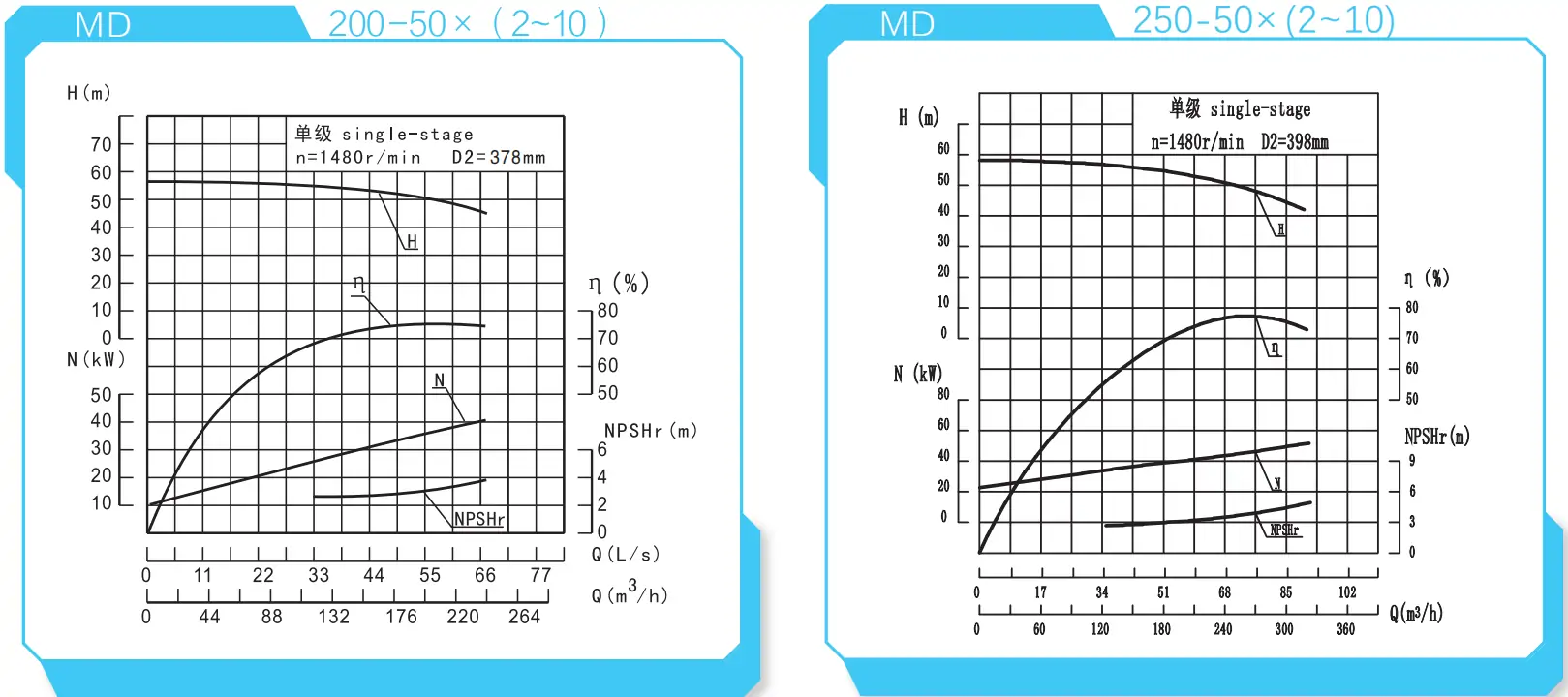
| 200-50×(2~10) | 2~10 | 120 | 33.3 | 1480 | 68.5 | 206.10 | Y4002-4 | 2.6 | Φ213 | 2210 | 378 |
| 2~10 | 200 | 55.6 | 1480 | 74.4 | 292.83 | Y4002-4 | 3.1 | Φ213 | 2210 | 378 | |
| 2~10 | 240 | 66.7 | 1480 | 72.6 | 324.10 | Y4002-4 | 3.9 | Φ213 | 2210 | 378 | |
| 250-50×(2~10) | 2~10 | 160 | 44.4 | 1480 | 65 | 372.95 | Y4005-4 | 2.8 | Φ213 | 2880 | 398 |
| 2~10 | 250 | 69.4 | 1480 | 77 | 442.37 | Y4005-4 | 3.6 | Φ213 | 2880 | 398 | |
| 2~10 | 300 | 83.3 | 1480 | 75.5 | 493.75 | Y4005-4 | 4.4 | Φ213 | 2880 | 398 | |
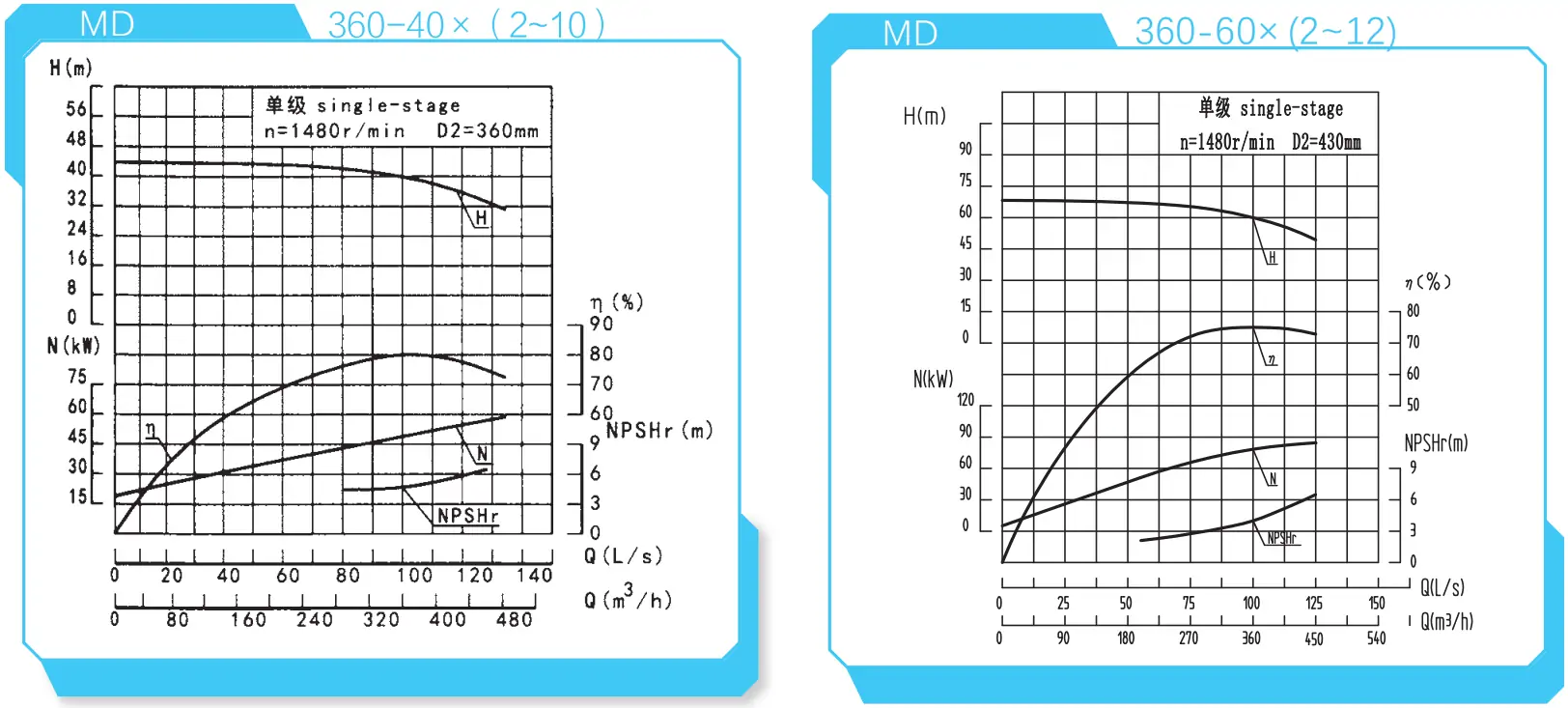
| 360-60×(2~12) | 2~12 | 300 | 83.3 | 1480 | 74 | 565.62 | Y4503-4 | 3.1 | Φ213 | 2098 | 500 |
| 2~12 | 360 | 100 | 1480 | 75 | 627.84 | Y4503-4 | 4.0 | Φ213 | 2098 | 500 | |
| 2~12 | 410 | 113.9 | 1480 | 74.5 | 659.85 | Y4503-4 | 5.3 | Φ213 | 2098 | 500 | |
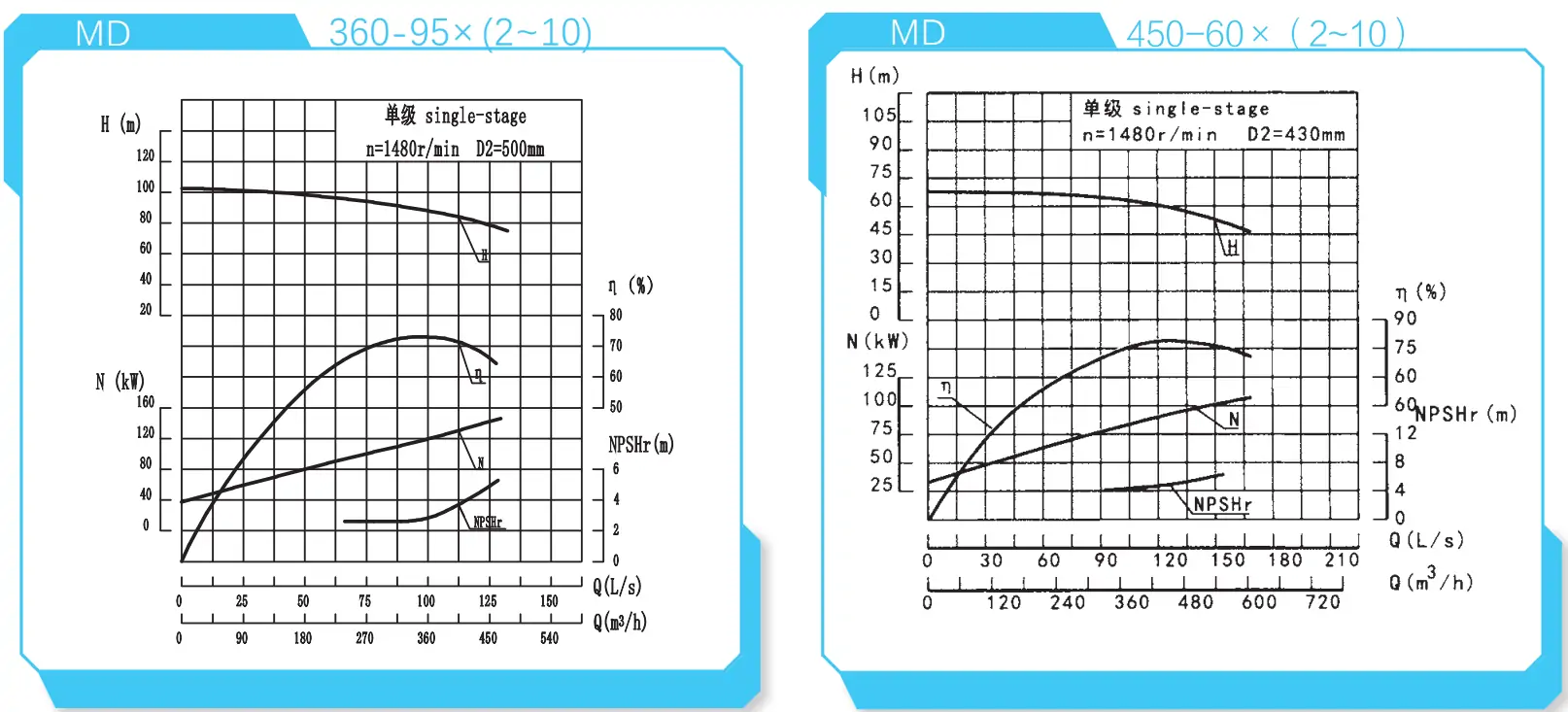
| 360-95×(2~10) | 2~10 | 280 | 77.8 | 1480 | 70 | 813.14 | Y5002-4 | 2.6 | Φ213 | 1875 | 500 |
| 2~10 | 360 | 100 | 1480 | 73 | 946.06 | Y5002-4 | 2.8 | Φ213 | 1875 | 500 | |
| 2~10 | 410 | 113.9 | 1480 | 71 | 1052.42 | Y5002-4 | 3.8 | Φ213 | 1875 | 500 | |
| 500-85×(2~10) | 2~10 | 375 | 104.2 | 1480 | 75 | 1321.63 | Y5602-4 | 3.5 | Φ213 | 3550 | 530 |
| 2~10 | 500 | 139.0 | 1480 | 76 | 1523.85 | Y5602-4 | 5.0 | Φ213 | 3550 | 530 | |
| 2~10 | 550 | 152.8 | 1480 | 72 | 1561.20 | Y5602-4 | 5.8 | Φ213 | 3550 | 530 |
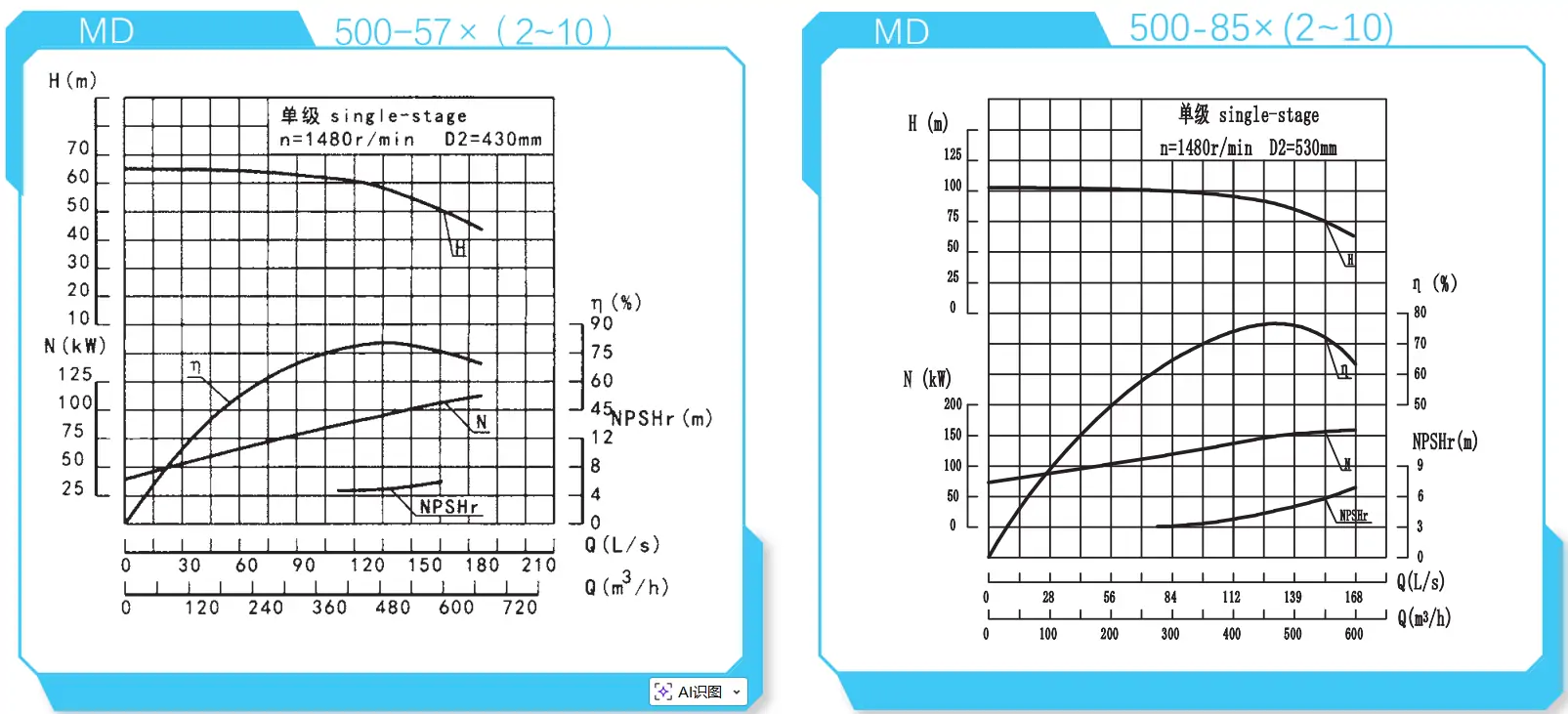
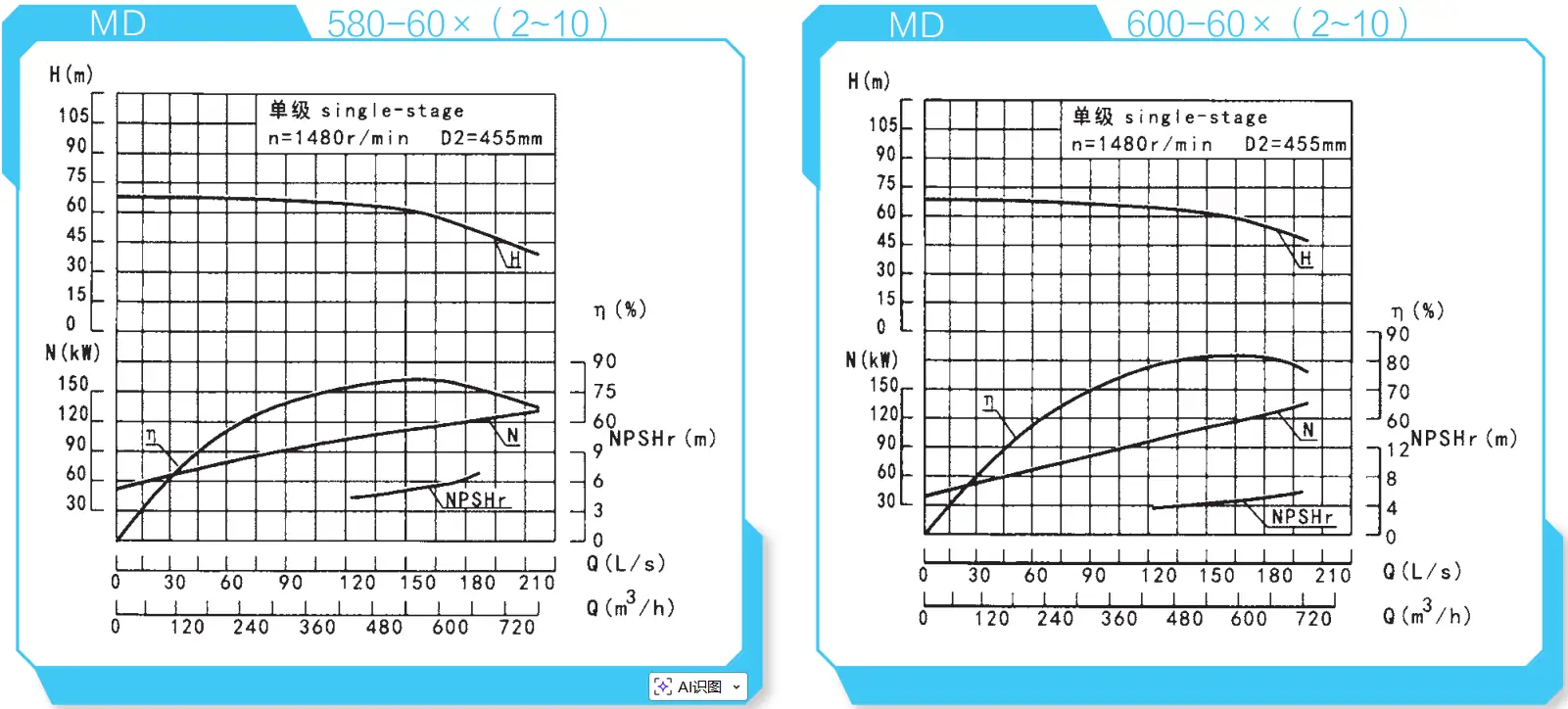
منحنى الأداء المرجعي
和-MD150-50x-210_1.webp)
_2.webp)
和-MD280-65x-212)_4.webp)
تركيب مضخة متعددة المراحل عالية الضغط عالية الضغط
عند تركيب هذا المنتج باستخدام نظام التوازن الذاتي ثلاثي العناصر، بالإضافة إلى استيفاء المتطلبات العامة، يجب ملاحظة النقاط التالية:
- 1) قم بتسوية سطح أساس المعدات باستخدام ميزان روحاني. بعد معالجة أسمنت الأساس، افحص ما إذا كانت فتحات القاعدة ومسامير التثبيت غير مثبتة.
- 2) بعد تجميع وحدة المحرك، والمعدات، والقاعدة، افحص بدقة التركز بين عمود دوران الوحدة وعمود دوران وحدة الدفع للتأكد من تطابق خطي المحورين؛ والتركيز بين عمود الدوران الرئيسي للوحدة وعمود الدوران الرئيسي لوحدة الدفع لضمان محاذاة مركزي العمودين.
- 3) أثناء تجميع وحدة المحرك والمعدات، تأكد من قيمة الخلوص المحوري بين أوجه الوصلة لكل من المعدات ووحدة القيادة.
- 4) يجب أن يكون لخطي أنابيب الشفط والتفريغ في المعدات دعامات منفصلة. ولا يمكن للمعدات أن تتحمل سوى قواها الداخلية ويجب ألا تتحمل أي قوى خارجية لمنع حدوث تلف.
تجميع المعدات
يتبع تجميع المعدات بشكل عام التسلسل العكسي للتفكيك. تؤثر جودة التجميع بشكل مباشر على القدرة التشغيلية للمعدات وعمر الخدمة ومعايير الأداء. انتبه إلى النقاط التالية أثناء التجميع:
- 1) الحفاظ على دقة التصنيع وخشونة سطح المكونات. تجنب الصدمات أو الخدوش أو الأضرار الأخرى. تأكد من نظافة مانع التسرب المستخدم في الختم. تطبيق قوة موحدة عند إحكام ربط البراغي والمسامير;
- 2) يتم ضمان المحاذاة بين مسار تدفق مخرج المكره ثلاثي الأبعاد ومسار تدفق مدخل دوارات التوجيه من خلال الأبعاد المحورية لكل مكون. وتؤثر جودة محاذاة مسار التدفق تأثيرًا مباشرًا على أداء المعدات؛ ولذلك، يجب عدم تعديل أبعاد المعدات بشكل تعسفي;
- 3) بعد التجميع، قم بتدوير دوّار المضخة يدويًا للتحقق من سلاسة الدوران داخل مبيت المضخة وتأكيد أن الموضع المحوري يفي بالمتطلبات المحددة.
لمزيد من مشكلات التثبيت الفني، يُرجى الاتصال بفريقنا.
البريد الإلكتروني: [email protected]
الهاتف +86-13651913727
الأعطال المحتملة وحلولها
| أعراض العطل | تحليل الأسباب | الحل |
|---|---|---|
| فشل في التهيئة، إبر مقياس الضغط ومقياس التفريغ تتأرجح بعنف | عدم كفاية مياه التحضير؛ تسرب الهواء في خط الأنابيب أو وصلات المقياس. | أعد الملء بماء تحضير كافٍ؛ استنفد الهواء تمامًا؛ افحص وصلات المقياس وموانع التسرب؛ أحكم ربط نقاط التسريب أو أصلحها. |
| فشل المضخة في التحضير، يظهر مقياس التفريغ فراغًا عاليًا | صمام القدم غير مفتوح أو مسدود؛ مقاومة مفرطة في أنبوب الشفط؛ رفع الشفط مرتفع للغاية. | ضبط وتنظيف صمام القدم؛ تنظيف أو استبدال أنبوب الشفط؛ تقليل ارتفاع الشفط. |
| يظهر مقياس الضغط الضغط، ولكن لا يوجد تصريف للمياه | مقاومة مفرطة في أنبوب التفريغ؛ اتجاه دوران غير صحيح؛ ممرات الدفاعة مسدودة أو تالفة؛ سرعة المضخة غير كافية. | فحص أو تقصير خط أنابيب التفريغ؛ تنظيف ممرات المكرهة أو استبدال المكرهة؛ فحص المحرك وزيادة سرعة المضخة. |
| معدل التدفق أقل من متطلبات التصميم | انسداد المضخة أو خط الأنابيب؛ تآكل مفرط في حلقة الختم؛ سرعة غير كافية. | افحص بحثًا عن وجود انسداد في ممر التدفق، نظف المضخة وخط الأنابيب؛ استبدل حلقة منع التسرب؛ قم بزيادة سرعة المضخة. |
| الاستهلاك المفرط للطاقة، وانقطاع مياه التوازن، وارتفاع درجة حرارة غرفة التوازن، وزيادة طاقة المحرك | الاحتكاك بين الجزء الدوار والجزء الثابت في المضخة؛ تآكل المكره؛ تآكل نظام التوازن الذاتي؛ التدفق الزائد للمضخة. | تحقق من عدم وجود انحناء في العمود؛ افحص مناطق الاحتكاك واستبدل المكرهة؛ قم بإصلاح أو استبدال مكونات التوازن الذاتي؛ قلل معدل التدفق. |
| ضجيج غير طبيعي داخل المضخة، لا يوجد تصريف للمياه | مقاومة مفرطة لأنبوب الشفط؛ فتح الصمام على نطاق واسع جدًا؛ دخول الهواء في جانب الشفط مما يسبب التجويف؛ درجة حرارة السائل عالية جدًا؛ عدم توازن الدوار أو العمود المثني أو عدم المحاذاة بين المضخة وعمود المحرك؛ ضعف الأساس. | فحص أنبوب الشفط وصمام القدم؛ إغلاق الصمام جزئيًا لتقليل التدفق؛ خفض ارتفاع التركيب؛ تبسيط أنابيب المدخل لتقليل الفاقد؛ سد تسربات الهواء؛ خفض درجة حرارة السائل؛ إحكام ربط المكونات المفكوكة؛ موازنة المكرهة عن طريق المعالجة الآلية؛ محاذاة المضخة والمحرك؛ تقوية الأساس. |
| اهتزاز النظام، ارتفاع درجة حرارة المحمل | اختلال المحاذاة بين المحرك والمضخة؛ عدم كفاية التشحيم أو تآكل المحمل؛ وجود تجويف. | محاذاة أعمدة المحرك والمضخة؛ تشحيم أو استبدال المحامل؛ تقليل معدل التدفق. |
ملاحظة: ينطبق جدول تحليل الأعطال هذا تحديدًا على أنظمة المضخات متعددة المراحل عالية الضغط. ارجع دائمًا إلى دليل التشغيل والصيانة الرسمي قبل إجراء أي صيانة أو تعديلات.
مزايا المضخة متعددة المراحل ذات الضغط العالي
الميزات التقنية
هيكل مُحسَّن للتطبيقات عالية الرأس ومتعددة المراحل مع تحكم مستقر في القوة المحورية وموثوقية تشغيلية عالية على المدى الطويل.
كفاءة عالية وتوفير في الطاقة
تضمن مكونات التدفق المصبوبة بدقة أبعاد مسار تدفق متسقة، مما يوفر كفاءة مقاسة تزيد عن 2% أعلى من المضخات التقليدية متعددة المراحل.
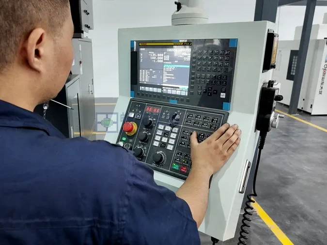
معدات التصنيع المتقدمة
تخضع الدوّارات الحرجة لفحص كل مرحلة على حدة وموازنة ديناميكية وفقًا لمعايير G2.5، مما يضمن تشغيل منخفض الاهتزاز ومنخفض الضوضاء.
اختيار المواد
يوازن تكوين المواد متعدد التدرجات بين مقاومة التآكل، ومقاومة التآكل، والتكلفة، والتكيف مع ظروف الأنفاق والتعدين المتنوعة.
تكوين مواد نظام الموازنة
تستخدم مكونات الموازنة سبائك عالية الكروم ومواد مقواة بالتفريغ، مما يوفر عمر تآكل أطول بكثير مقارنةً بالتكوينات القياسية.
مبدأ نظام التوازن الذاتي
يقلل الضبط التلقائي للقوة المحورية من حركة الدوار والتآكل، مما يحافظ على ثبات الكفاءة وارتفاع درجة حرارة المحمل.
التطبيق
تتميز المضخة متعددة المراحل عالية الضغط بهيكل موازنة من نوع الأسطوانة. يستخدم هذا التصميم الموازن من نوع الأسطوانة تقنيات جديدة لمعالجة المواد للقضاء على نقاط الضعف الشائعة في المضخات التقليدية متعددة المراحل، مثل معدلات التآكل العالية ومتطلبات الصيانة المتكررة.
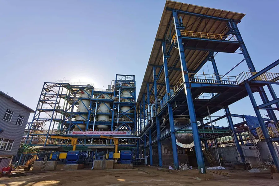
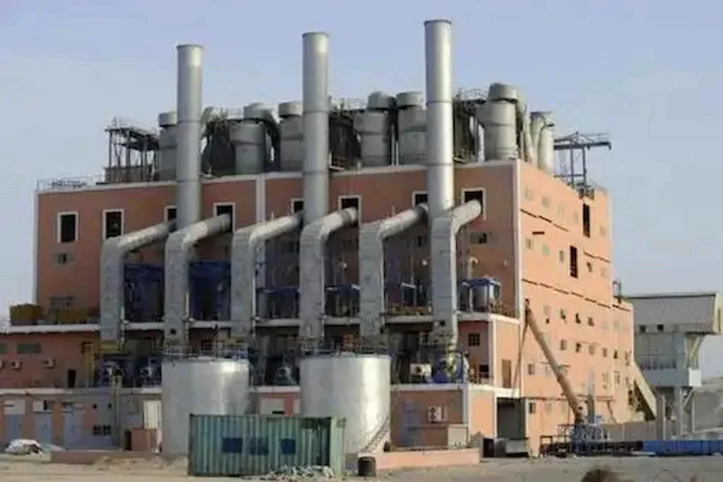
يُستخدم هذا المنتج على نطاق واسع في التطبيقات المعقدة بما في ذلك تحلية مياه البحر، واستخراج المياه المالحة، والمعالجة الكيميائية للملح، وأنظمة مياه تغذية الغلايات، والصرف منخفض التجويف، ونقل النفط الخام في حقول النفط، وعمليات درع الأنفاق التي تتضمن وسائط محملة بالطمي بشكل كبير، وتصريف المناجم تحت الأرض.

حفر الأنفاق والهندسة تحت الأرض
مناسبة لعمليات تصريف أعمدة المناجم العميقة وعمليات التعدين، وقادرة على تحمل ظروف التشغيل عالية الرفع والحمولة العالية على المدى الطويل.
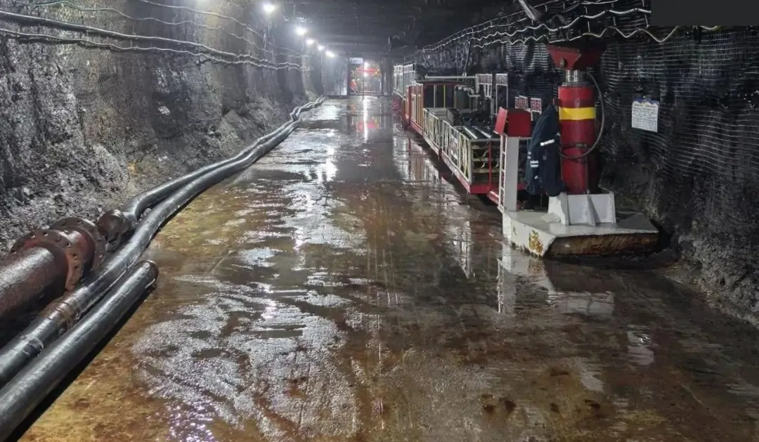
التعدين وصرف الألغام
مناسبة لعمليات تصريف أعمدة المناجم العميقة وعمليات التعدين، وقادرة على تحمل ظروف التشغيل عالية الرفع والحمولة العالية على المدى الطويل.
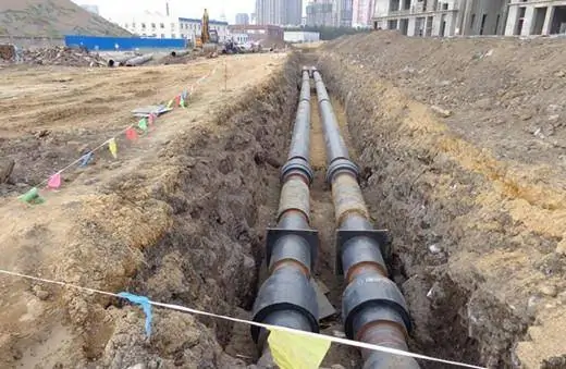
إمدادات المياه البلدية والصناعية والصرف الصحي والصرف الصحي
تستخدم لإمدادات المياه في المباني الشاهقة، ونقل المياه لمسافات طويلة، ومياه تركيب النظام الصناعي. يتميز بالتشغيل المستقر وتكاليف الصيانة المنخفضة.
الشركة المصنعة للمضخات متعددة المراحل عالية الضغط الاحترافية في الصين
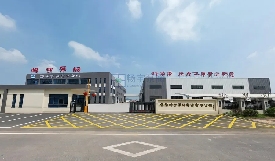
تتمتع شركة Changyu Pump Industry بأكثر من 22 عامًا من الخبرة في تصميم وتصنيع مضخات الطرد المركزي متعددة المراحل، وهي متخصصة في حلول الضخ الموثوقة للتطبيقات الصناعية الصعبة. وبفضل مرافق الإنتاج المتقدمة، وفريق هندسي متمرس، وأنظمة صارمة لمراقبة الجودة، نقدم مضخات مصممة للرأس العالي، والتشغيل المستمر، وعمر الخدمة الطويل.
لدينا المضخات متعددة المراحل عالية الضغط صُممت مضخات Changyu لبناء الأنفاق، ونزح المياه من المناجم، وإمدادات المياه الصناعية، وتطبيقات المباني الشاهقة، حيث يكون الأداء المستقر، والاستخدام الفعال للطاقة، والتحكم الدقيق في القوة المحورية أمرًا بالغ الأهمية. تتميز مضخات Changyu بتصميمات هيدروليكية مُحسَّنة ومواد قوية وأنظمة موازنة متقدمة، وتضمن التشغيل الآمن والفعال وطويل الأجل في ظل ظروف العمل القاسية.
اتصل بنا اليوم للحصول على عرض أسعار مخصص أو دعم فني احترافي - مهندسونا مستعدون لمساعدتك في اختيار المضخة المناسبة لمشروعك.
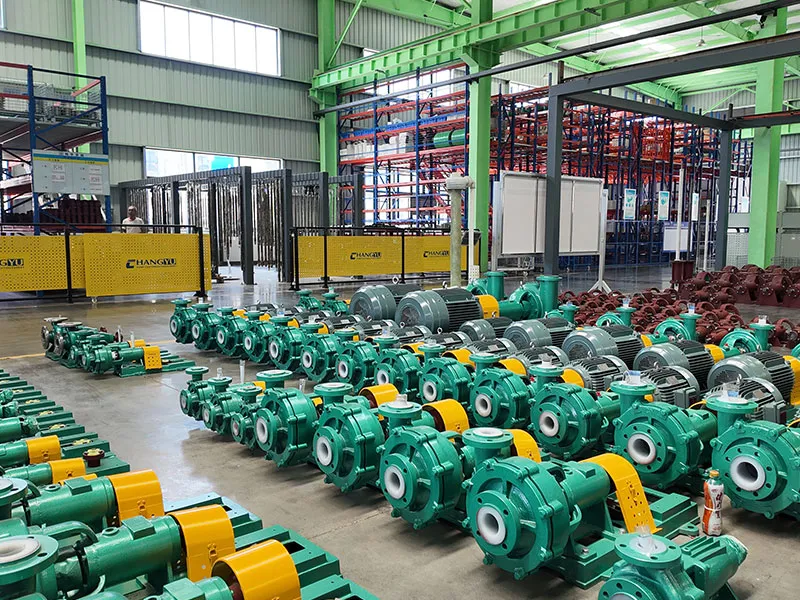
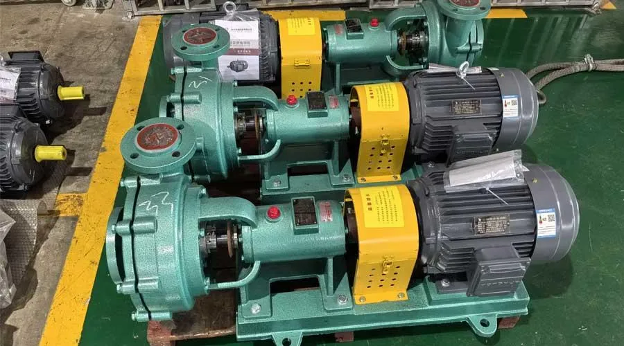
عرض المصنع


الأسئلة الشائعة

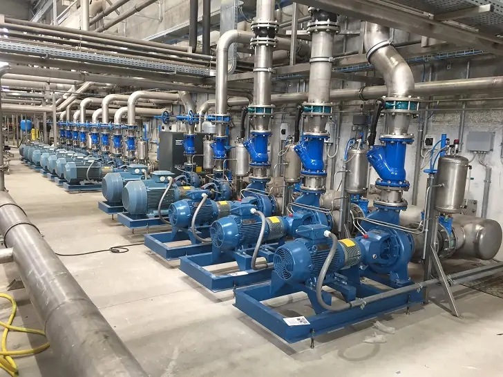
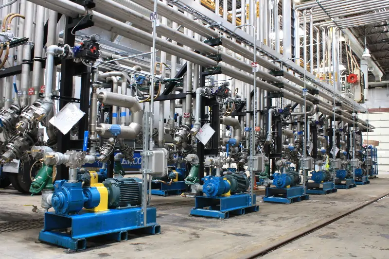
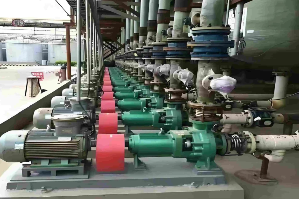
المشاريع

اطلب عرض أسعار مجاني
يُرجى ملء تفاصيل السائل الذي يتم ضخه، بما في ذلك التدفق والرأس والجاذبية النوعية ودرجة الحرارة، حتى نتمكن من التوصية بأفضل مضخة وتقديم عرض أسعار دقيق.