

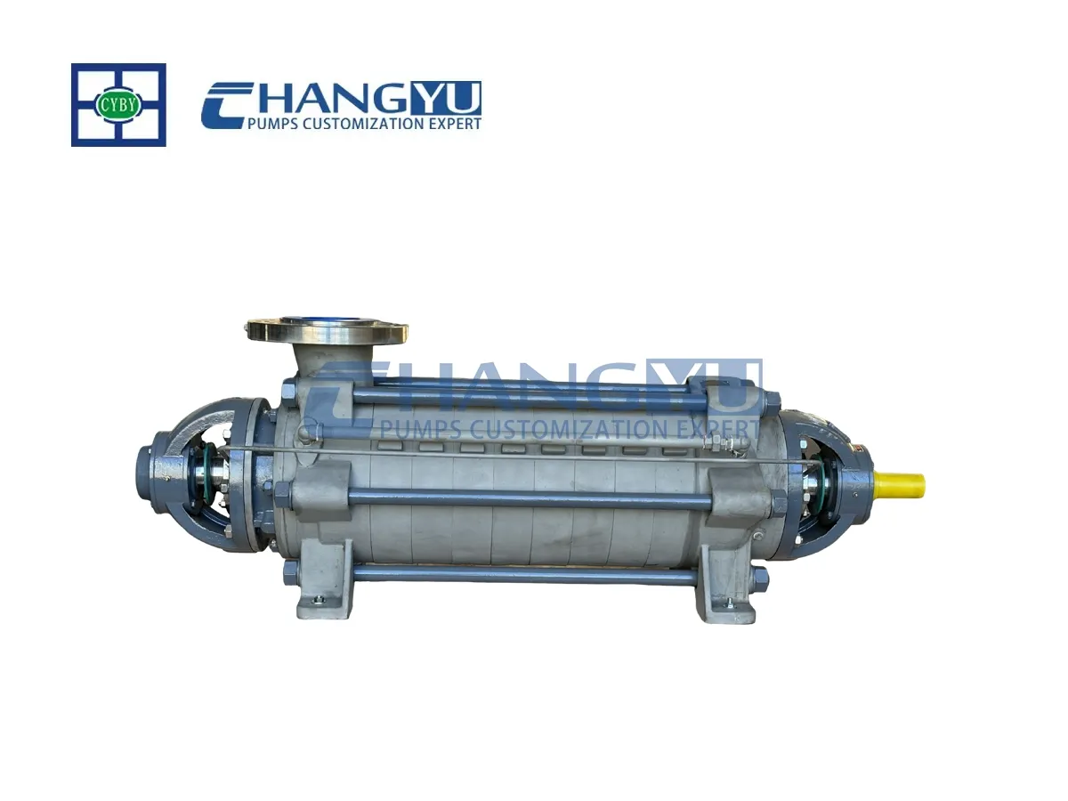


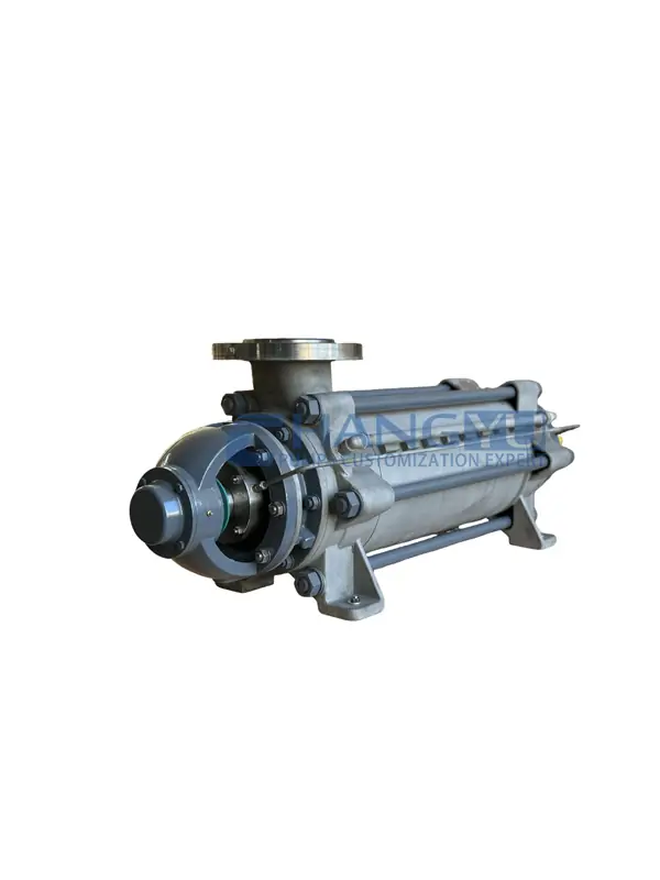
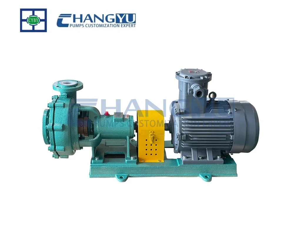
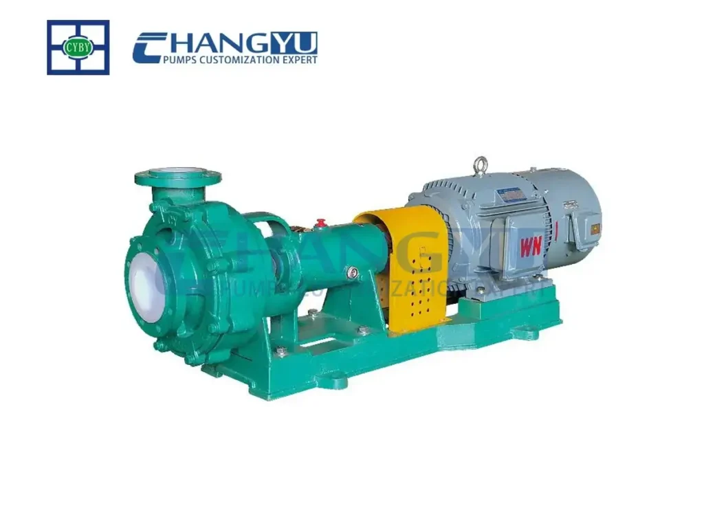
Bomba multietapa de alta presión serie MD
La bomba multietapa de alta presión de la serie MD es un tipo de bomba centrífuga multietapa segmentada que cuenta con dos o más impulsores montados en el eje. La salida de la primera etapa se comunica con la entrada de la segunda etapa, mientras que la salida de la segunda etapa se conecta a la entrada de la tercera etapa. Esta configuración en serie conforma la bomba centrífuga multietapa.
Apto para el transporte de aguas subterráneas procedentes de explotaciones mineras o de aguas residuales municipales que contengan partículas sólidas con una concentración ≤1,51 % en peso, un diámetro de partícula ≤0,5 mm y una temperatura inferior a 80 °C.
Bombas Changyu te ayuda a personalizar tu producción.
|
Rango de caudal: |
3,75 m³/h ~ 850 m³/h |
|---|---|
|
Rango de cabezas: |
19 m ~ 816 m |
|
Potencia del motor: |
7,5 kW ~ 450 kW |
|
Velocidad: |
2980 ~ 1480 rpm |
|
Rango de temperatura medio: |
80 °C |
|
Materiales personalizables: |
Hierro fundido, hierro dúctil, acero aleado resistente al desgaste, hierro fundido aleado resistente al desgaste, acero resistente al calor, diversos grados de acero inoxidable, aleaciones de titanio, cerámica, etc. |
Introducción
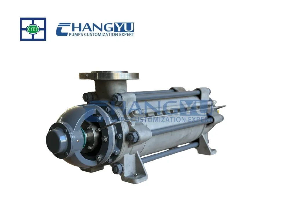
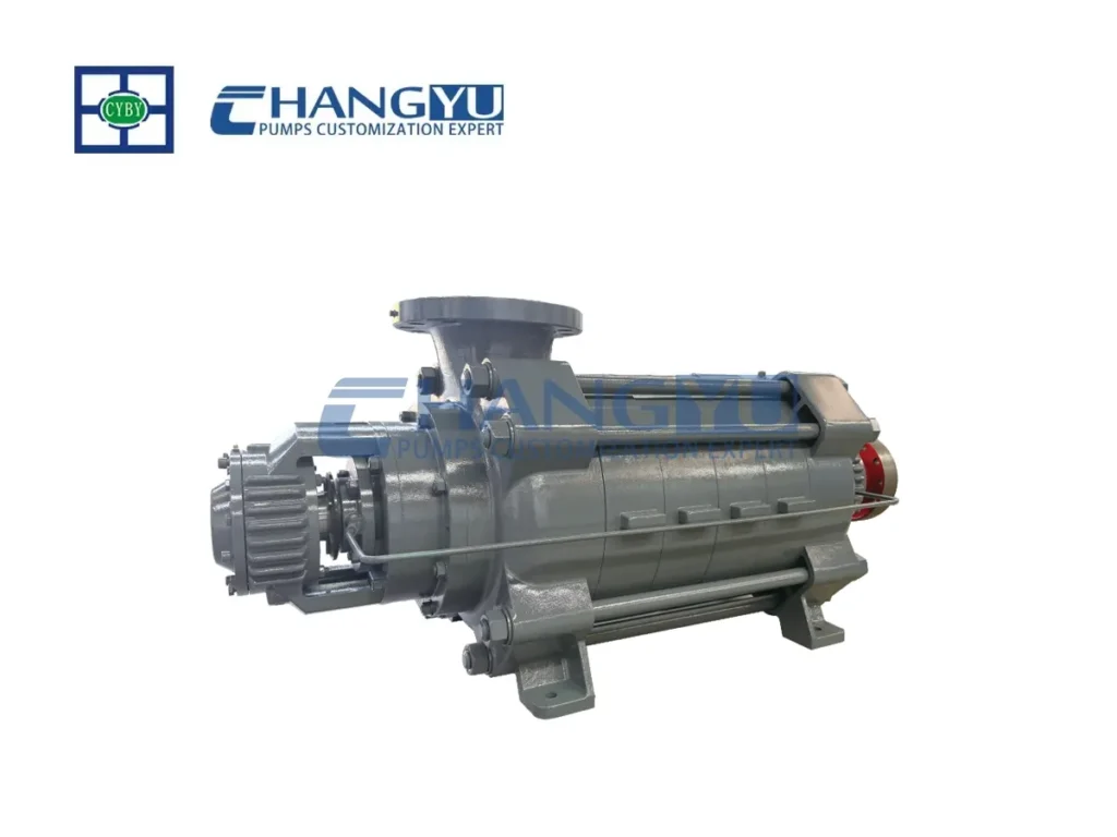
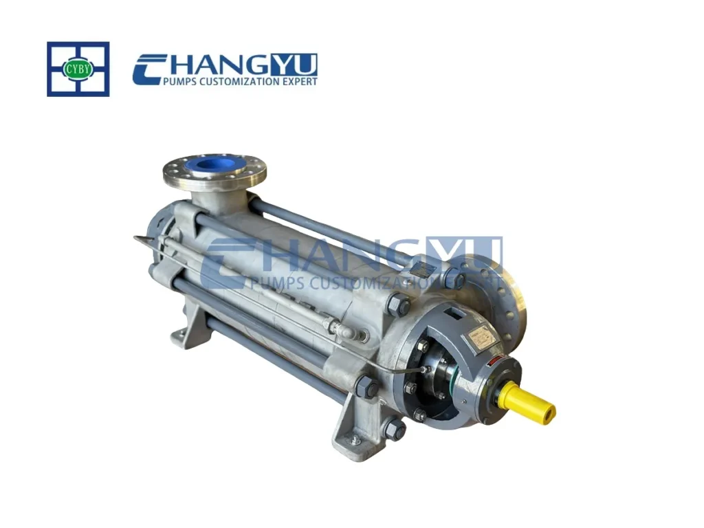
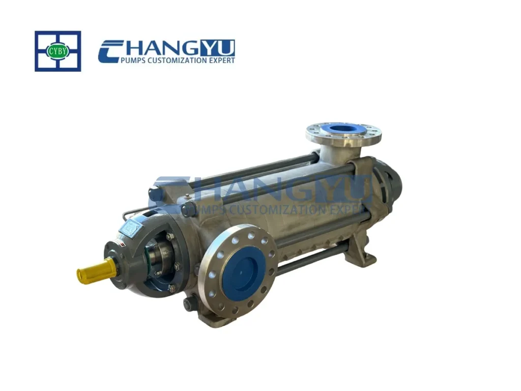
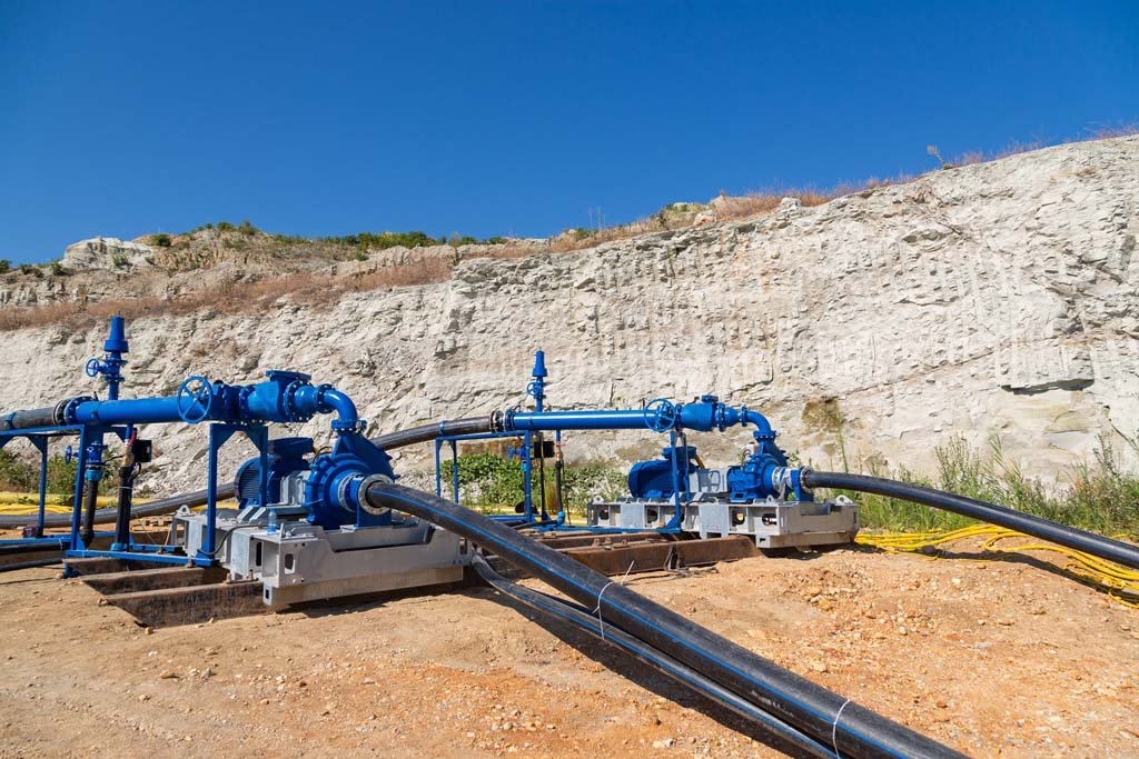
La bomba multietapa de alta presión de la serie MD es una bomba horizontal, de succión simple, con estructura de anillos segmentados bomba centrífuga. Utiliza el modelo hidráulico más avanzado y confiable disponible en la actualidad y se emplea habitualmente en ingeniería de túneles, minería y proyectos de excavación de túneles.
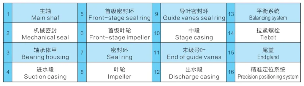
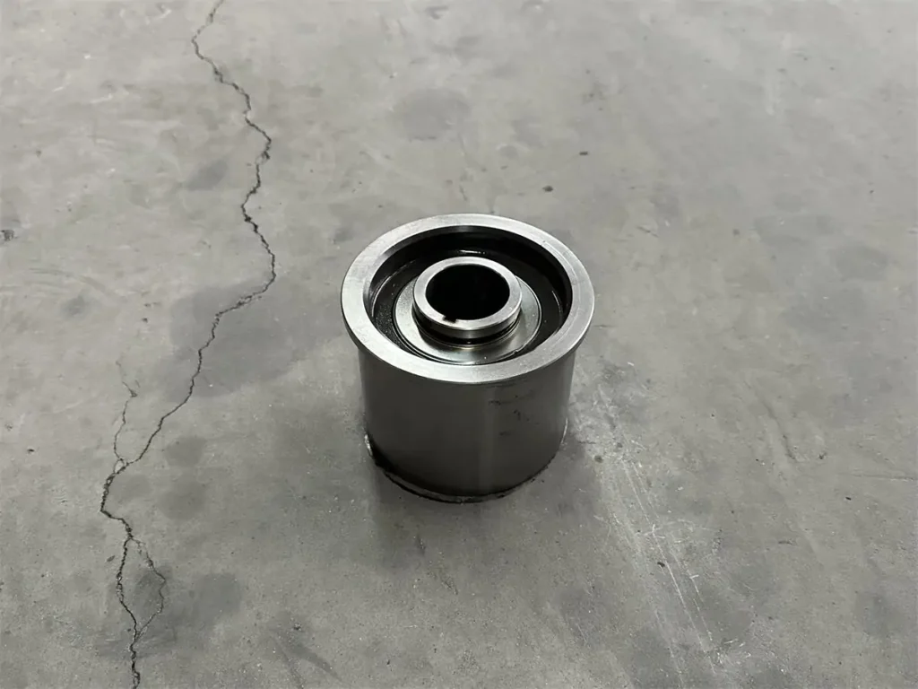
Para el equilibrio de fuerzas axiales, Changyu Pumps utiliza un avanzado sistema de equilibrio de cuatro etapas que cuenta con una estructura de tambor anular de eficacia probada, validada a lo largo de más de una década de aplicación práctica. En combinación con una tecnología de posicionamiento preciso de la holgura axial, este sistema logra un equilibrio total de las fuerzas axiales, lo que garantiza un funcionamiento estable y confiable.
La bomba multietapa de alta presión de la serie MD también ofrece ventajas tales como un amplio rango de alta eficiencia, un ciclo de disminución de la eficiencia prolongado, un amplio espectro de rendimiento, un funcionamiento suave, bajo nivel de ruido, una larga vida útil y una instalación y mantenimiento sencillos. Satisface las exigencias duales de alta eficiencia, ahorro de energía y durabilidad estable en diversas aplicaciones industriales.
Dependiendo del medio transportado, el producto se puede personalizar con los materiales adecuados para garantizar un funcionamiento seguro y confiable, incluso en condiciones adversas que impliquen corrosión y desgaste.
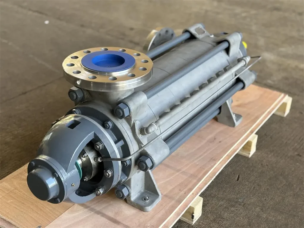
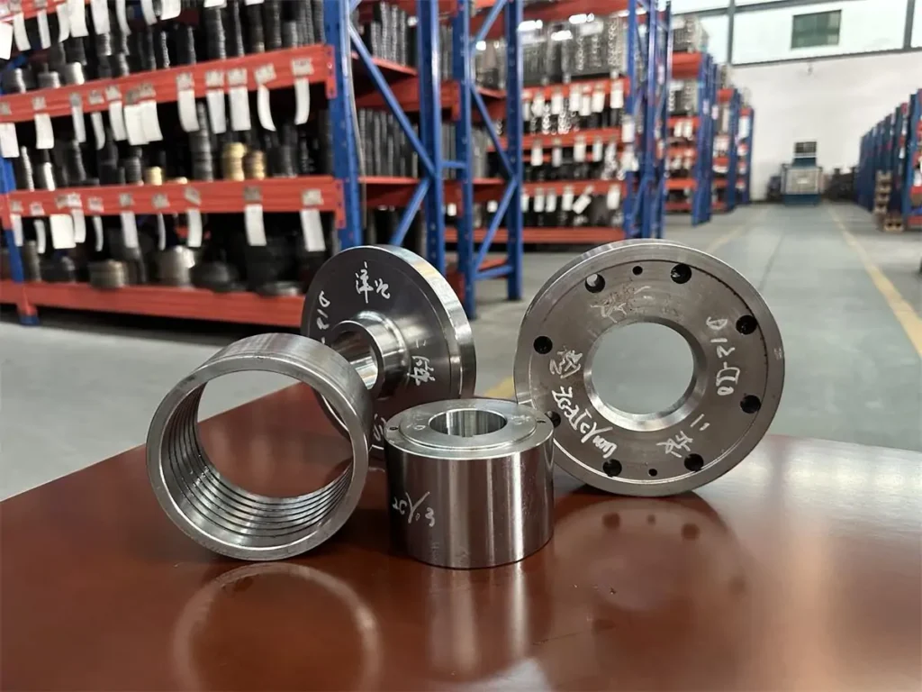
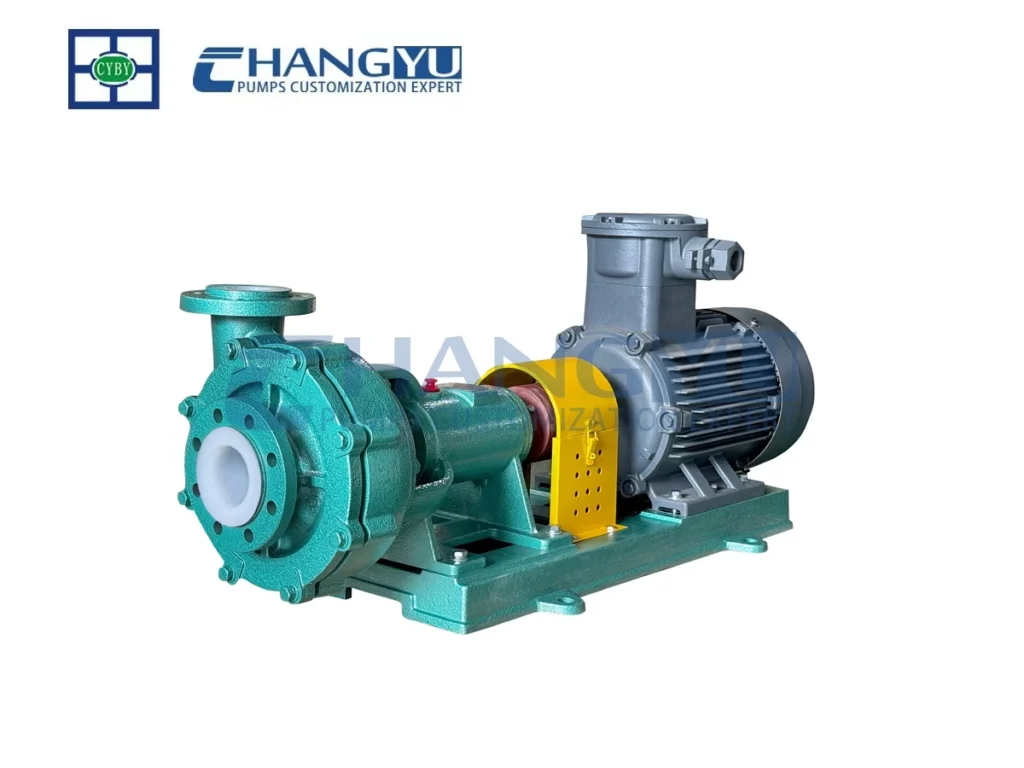
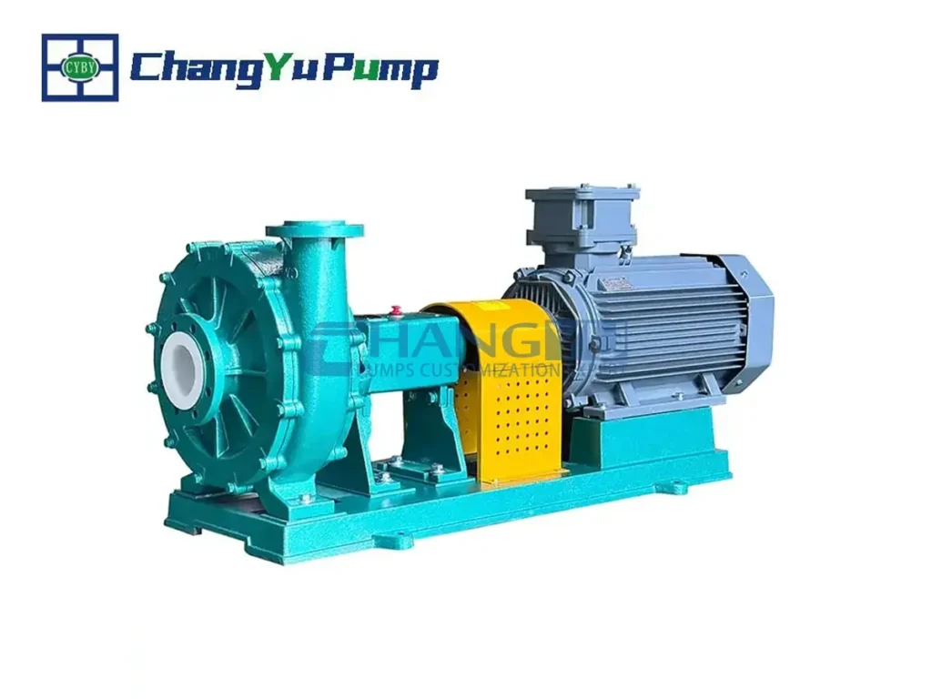
Componentes de una bomba multietapa de alta presión
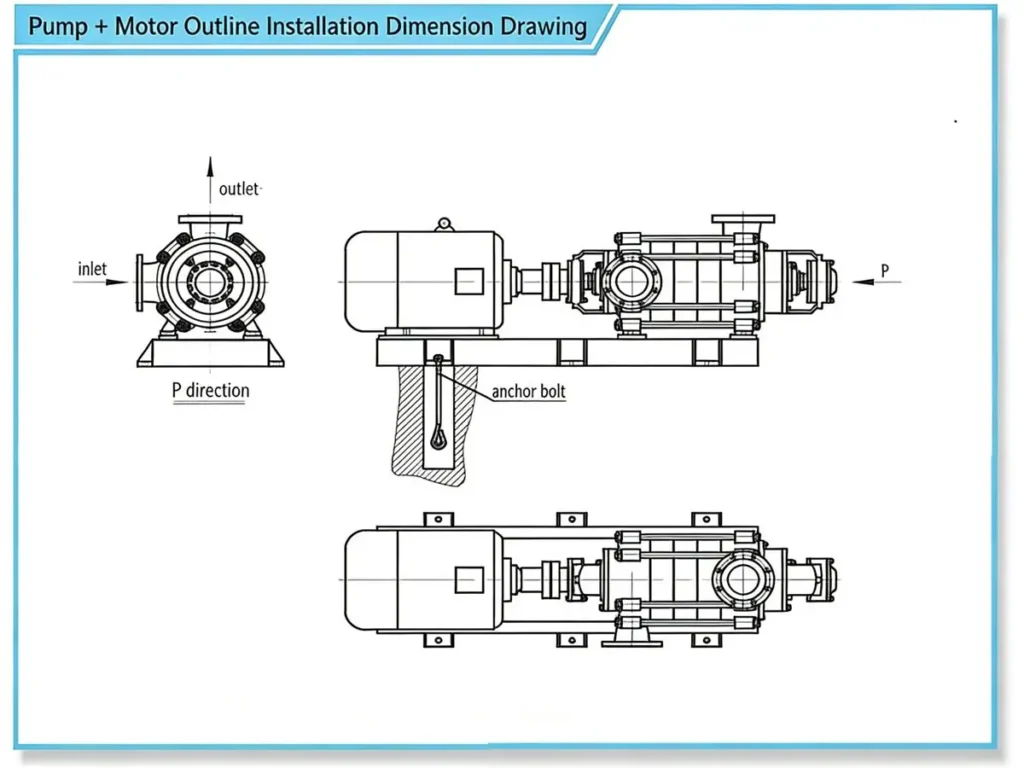
La bomba industrial MD es una bomba centrífuga multietapa segmentada, de succión simple y disposición horizontal. La entrada de succión es horizontal, mientras que la salida de descarga es vertical hacia arriba. Las secciones de la carcasa de la bomba —incluidas la sección de entrada, la sección intermedia y la sección de descarga— se ensamblan en una sola unidad mediante pernos de tensión. Se instalan conjuntos de cojinetes en ambos extremos, y el número de etapas se selecciona en función de la altura de elevación requerida por la bomba.
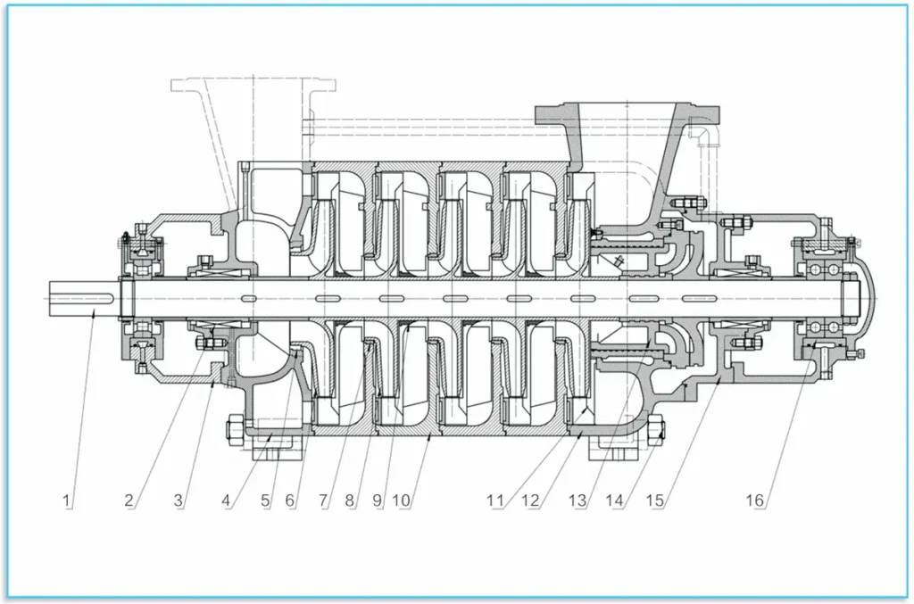
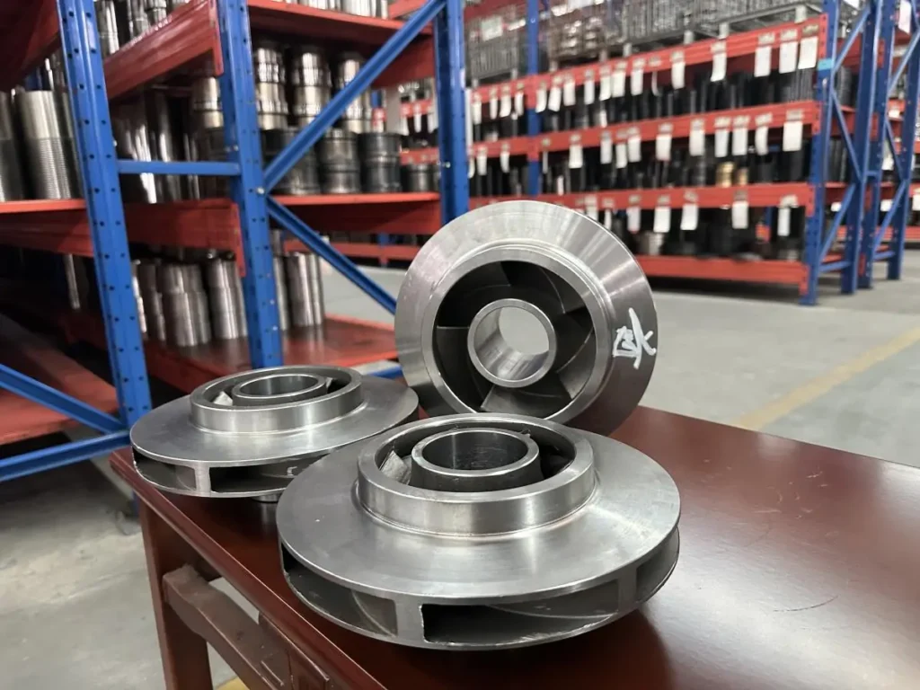
El conjunto del rotor se compone principalmente del eje y de los componentes montados en él, entre los que se incluyen los impulsores, los manguitos del eje y el sistema de equilibrado. El número de impulsores corresponde al número de etapas de la bomba. Las piezas montadas en el eje se fijan a este mediante chavetas planas y tuercas de eje. Todo el rotor se apoya en un rodamiento de rodillos en el extremo de accionamiento y en dos rodamientos de bolas en el extremo no accionado. Si se utiliza un cojinete deslizante de eje, se requiere además un soporte de posicionamiento de precisión en el extremo no accionado. El cojinete deslizante del extremo no accionado requiere un soporte de posicionamiento de precisión adicional. Los rodamientos no soportan fuerzas axiales; un sistema de equilibrado tipo tambor contrarresta las fuerzas axiales desequilibradas.
Las superficies de sellado entre la sección de entrada, la sección intermedia y la sección de salida de la bomba utilizan sellador o juntas tóricas. Los anillos de sellado y los manguitos de los álabes guía se instalan entre el conjunto del rotor y los componentes fijos. Reemplace los anillos de sellado y los manguitos de los álabes guía de inmediato cuando su desgaste afecte el rendimiento de la bomba. Cuando el desgaste de los anillos de sellado o de los manguitos de las paletas guía afecte el rendimiento de la bomba, deben reemplazarse de inmediato. Las opciones de sellado del eje incluyen sellos mecánicos y empaques. Cuando se utilicen empaques, el anillo de empaque debe colocarse correctamente y la tensión del empaque debe ajustarse adecuadamente.
Todos los componentes de sellado de la bomba se encuentran dentro de una cámara sellada presurizada con agua para proporcionar sellado, refrigeración o lubricación. Se ha instalado un manguito de eje reemplazable en el sello del eje para proteger el eje de la bomba. Esta serie cuenta con conjuntos de rotor sin holgura axial. Por lo general, están equipadas con rodamientos y lubricación por aceite seco. Las bombas de esta serie son accionadas directamente por el motor primario a través de un acoplamiento elástico. Visto desde el extremo del motor, la bomba gira en sentido horario.
(Los clientes que tengan requisitos especiales en cuanto a los materiales o la estructura de la bomba pueden ponerse en contacto con nuestra empresa. Podemos modificar la orientación de la entrada y la salida de la bomba según las necesidades del cliente e implementar configuraciones y funciones de salida múltiple para esta serie.)
Material de la pieza moldeada
Las bombas centrífugas multietapa con segmentos anulares de la serie MD se pueden personalizar con diferentes materiales. Las principales configuraciones de materiales son las siguientes:
| Artículo | Agua limpia | Agua potable | Aguas residuales | Agua caliente | Agua de mar |
|---|---|---|---|---|---|
| Carcasa | Hierro gris (HT250) | S.S. 304 | Hierro dúctil (QT500) | Acero fundido | Dúplex de acero inoxidable 2205 |
| Impulsor y anillo | Hierro gris (HT250) | S.S. 304 | Hierro dúctil (QT500) | 2Cr13 | Dúplex de acero inoxidable 2205 |
| Difusor | Hierro gris (HT250) | S.S. 304 | Hierro dúctil (QT500) | 2Cr13 | Dúplex de acero inoxidable 2205 |
| Eje | C.S. 45 | S.S. 304 | 40Cr | 40Cr | Dúplex de acero inoxidable 2205 |
| Manguito de eje | C.S. 45 | S.S. 304 | S.S. 304 | S.S. 304 | Dúplex de acero inoxidable 2205 |
Nota: La lista detallada de materiales se basará en las condiciones del líquido y del terreno.
Los materiales personalizables para los componentes de flujo continuo incluyen: hierro fundido, hierro dúctil, acero aleado resistente al desgaste, hierro fundido aleado resistente al desgaste, acero resistente al calor, diversos grados de acero inoxidable, aleaciones de titanio, cerámicas y otros materiales.
Especificaciones
Descripción del modelo
EX:MD600 – 60×6
MD — Bomba centrífuga multietapa de tambor resistente al desgaste
600 — El punto de diseño de la capacidad es de 600 m³/h
60 — La altura de bombeo nominal de la etapa única es de 60 m
6 — La etapa de la bomba es la 6
EX:150 MD 30×7
150 — el diámetro de la entrada de la bomba es de 150 mm
MD — Bomba centrífuga multietapa de tambor resistente al desgaste
30 — La altura de diseño de la bomba de una etapa es de 30 m
7—La etapa de la bomba es la 7
A continuación se indican las dimensiones estándar de nuestros modelos de bombas para su referencia. Para condiciones de funcionamiento específicas, póngase en contacto con nuestro equipo técnico para obtener una solución más precisa y adecuada.
| Modelo | Etapas | Caudal (m³/h) | Jefe (m) | Velocidad (rpm) | Eficiencia (%) | Potencia en el eje (kW) | Modelo de motor | NPSHr (m) | Diámetro del impulsor (mm) | Peso de la bomba (kg) | Peso del motor (kg) |
|---|---|---|---|---|---|---|---|---|---|---|---|
| 6-25×(2~12) | 2 | 3.75 | 51 | 2950 | 35 | 1.84 | Y100L-2 | 2.0 | Φ139,5 | 77.2 | 33 |
| 2 | 6.3 | 50 | 2950 | 48 | 2.08 | Y100L-2 | 2.0 | Φ139,5 | 77.2 | 33 | |
| 2 | 7.5 | 49 | 2950 | 48 | 2.08 | Y100L-2 | 2.0 | Φ139,5 | 77.2 | 33 | |
| 6-50×(2~14) | 2~14 | 3.75 | 51 | 2950 | 35 | 1.84 | Y100L-2 | 2.0 | Φ139,5 | 111.5 | 117 |
| 2~14 | 6.3 | 50 | 2950 | 48 | 2.08 | Y100L-2 | 2.0 | Φ139,5 | 111.5 | 117 | |
| 2~14 | 7.5 | 49 | 2950 | 48 | 2.08 | Y100L-2 | 2.0 | Φ139,5 | 111.5 | 117 | |
| 48-50 × (2-12) | 2 | 35 | 110 | 2980 | 56 | 18.72 | Y200L1-2 | 2.5 | Φ210 | 240 | 267 |
| 2 | 48 | 100 | 2980 | 67 | 19.50 | Y200L1-2 | 2.8 | Φ210 | 240 | 267 | |
| 2 | 60 | 84 | 2980 | 68 | 20.18 | Y200L1-2 | 3.2 | Φ210 | 240 | 267 | |
| 60-50 × (2~12) | 2 | 40 | 109 | 2950 | 56 | 21.22 | Y200L1-2 | 3.8 | Φ210 | 310 | 332 |
| 2 | 60 | 100 | 2950 | 67 | 24.40 | Y200L1-2 | 4.0 | Φ210 | 310 | 332 | |
| 2 | 75 | 90 | 2950 | 68 | 27.05 | Y200L1-2 | 4.2 | Φ210 | 310 | 332 | |
| 85-45×(2~9) | 2~9 | 55 | 20 | 2950 | 72 | 48.53 | Y315S-2 | 3.2 | Φ200 | 253.3 | 500 |
| 2~9 | 85 | 15 | 2950 | 70 | 60.75 | Y315M-2 | 3.2 | Φ200 | 253.3 | 500 | |
| 100-30×(2~10) | 2~10 | 70 | 19.4 | 2950 | 70 | 65.34 | Y315S-2 | 4.1 | Φ200 | 745 | 875 |
| 2~10 | 100 | 27.7 | 2950 | 75 | 76.30 | Y355M1-2 | 3.2 | Φ213 | 832 | 1550 | |
| 150-50×(2~10) | 2~10 | 100 | 33.3 | 1480 | 68.5 | 103.05 | Y315L2-4 | 2.6 | Φ213 | 1250 | 378 |
| 2~10 | 150 | 55.6 | 1480 | 74.4 | 146.41 | Y315L2-4 | 3.1 | Φ213 | 1250 | 378 | |
| 2~10 | 200 | 66.7 | 1480 | 72.6 | 162.05 | Y315L2-4 | 3.9 | Φ213 | 1250 | 378 | |
| 200-50 × (2~10) | 2~10 | 120 | 33.3 | 1480 | 68.5 | 206.10 | Y4002-4 | 2.6 | Φ213 | 2210 | 378 |
| 2~10 | 200 | 55.6 | 1480 | 74.4 | 292.83 | Y4002-4 | 3.1 | Φ213 | 2210 | 378 | |
| 2~10 | 240 | 66.7 | 1480 | 72.6 | 324.10 | Y4002-4 | 3.9 | Φ213 | 2210 | 378 | |
| 250-50×(2~10) | 2~10 | 160 | 44.4 | 1480 | 65 | 372.95 | Y4005-4 | 2.8 | Φ213 | 2880 | 398 |
| 2~10 | 250 | 69.4 | 1480 | 77 | 442.37 | Y4005-4 | 3.6 | Φ213 | 2880 | 398 | |
| 2~10 | 300 | 83.3 | 1480 | 75.5 | 493.75 | Y4005-4 | 4.4 | Φ213 | 2880 | 398 | |
| 360-60×(2~12) | 2~12 | 300 | 83.3 | 1480 | 74 | 565.62 | Y4503-4 | 3.1 | Φ213 | 2098 | 500 |
| 2~12 | 360 | 100 | 1480 | 75 | 627.84 | Y4503-4 | 4.0 | Φ213 | 2098 | 500 | |
| 2~12 | 410 | 113.9 | 1480 | 74.5 | 659.85 | Y4503-4 | 5.3 | Φ213 | 2098 | 500 | |
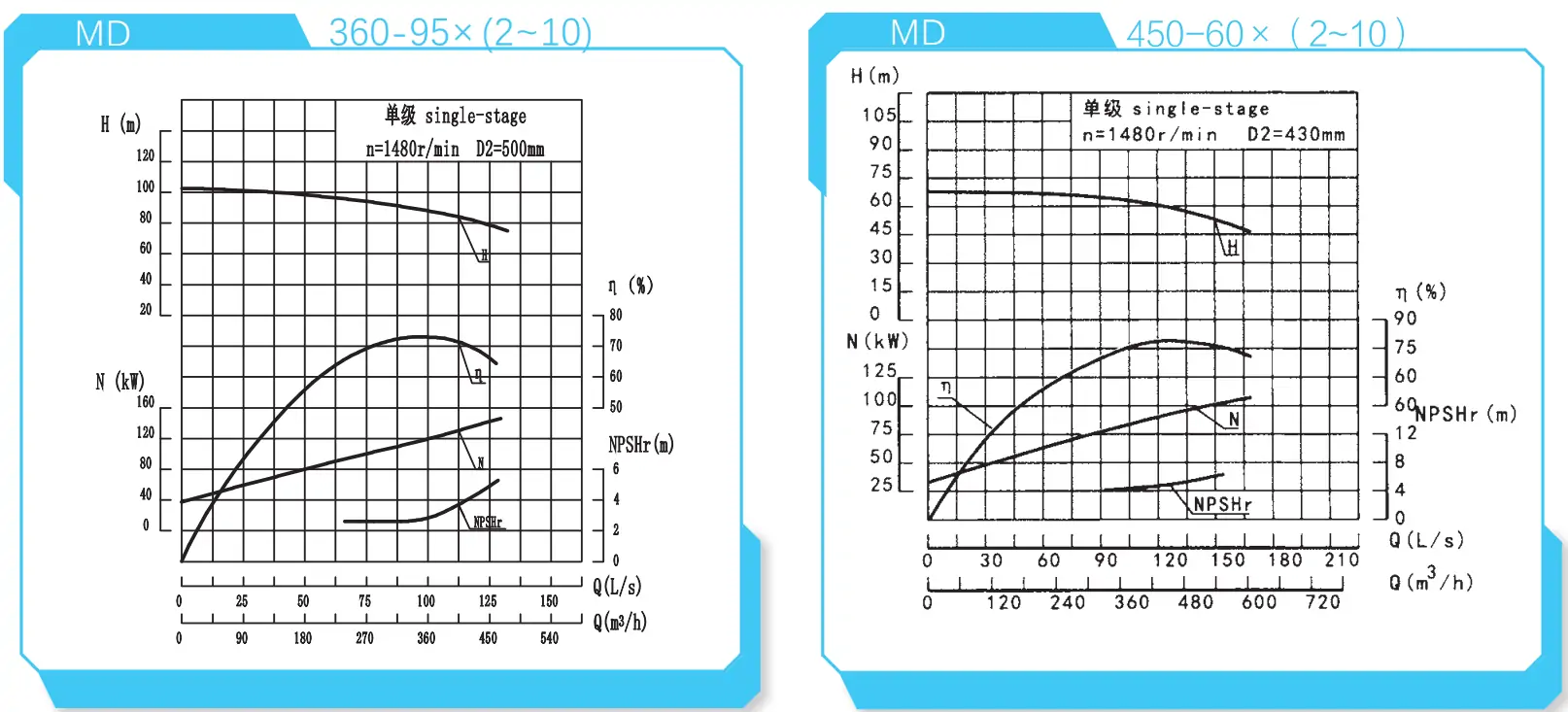
| 360-95×(2~10) | 2~10 | 280 | 77.8 | 1480 | 70 | 813.14 | Y5002-4 | 2.6 | Φ213 | 1875 | 500 |
| 2~10 | 360 | 100 | 1480 | 73 | 946.06 | Y5002-4 | 2.8 | Φ213 | 1875 | 500 | |
| 2~10 | 410 | 113.9 | 1480 | 71 | 1052.42 | Y5002-4 | 3.8 | Φ213 | 1875 | 500 | |
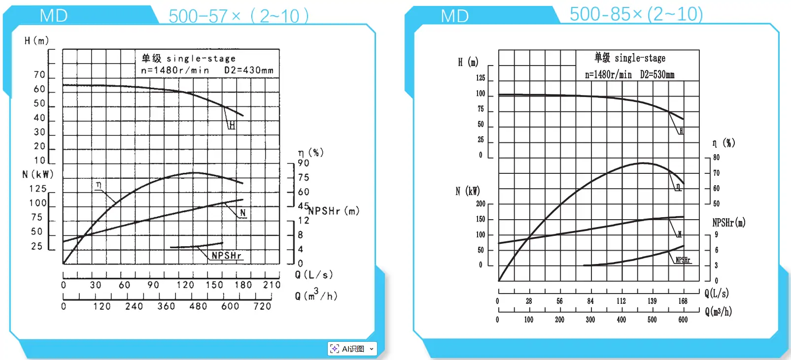
| 500-85×(2~10) | 2~10 | 375 | 104.2 | 1480 | 75 | 1321.63 | Y5602-4 | 3.5 | Φ213 | 3550 | 530 |
| 2~10 | 500 | 139.0 | 1480 | 76 | 1523.85 | Y5602-4 | 5.0 | Φ213 | 3550 | 530 | |
| 2~10 | 550 | 152.8 | 1480 | 72 | 1561.20 | Y5602-4 | 5.8 | Φ213 | 3550 | 530 |
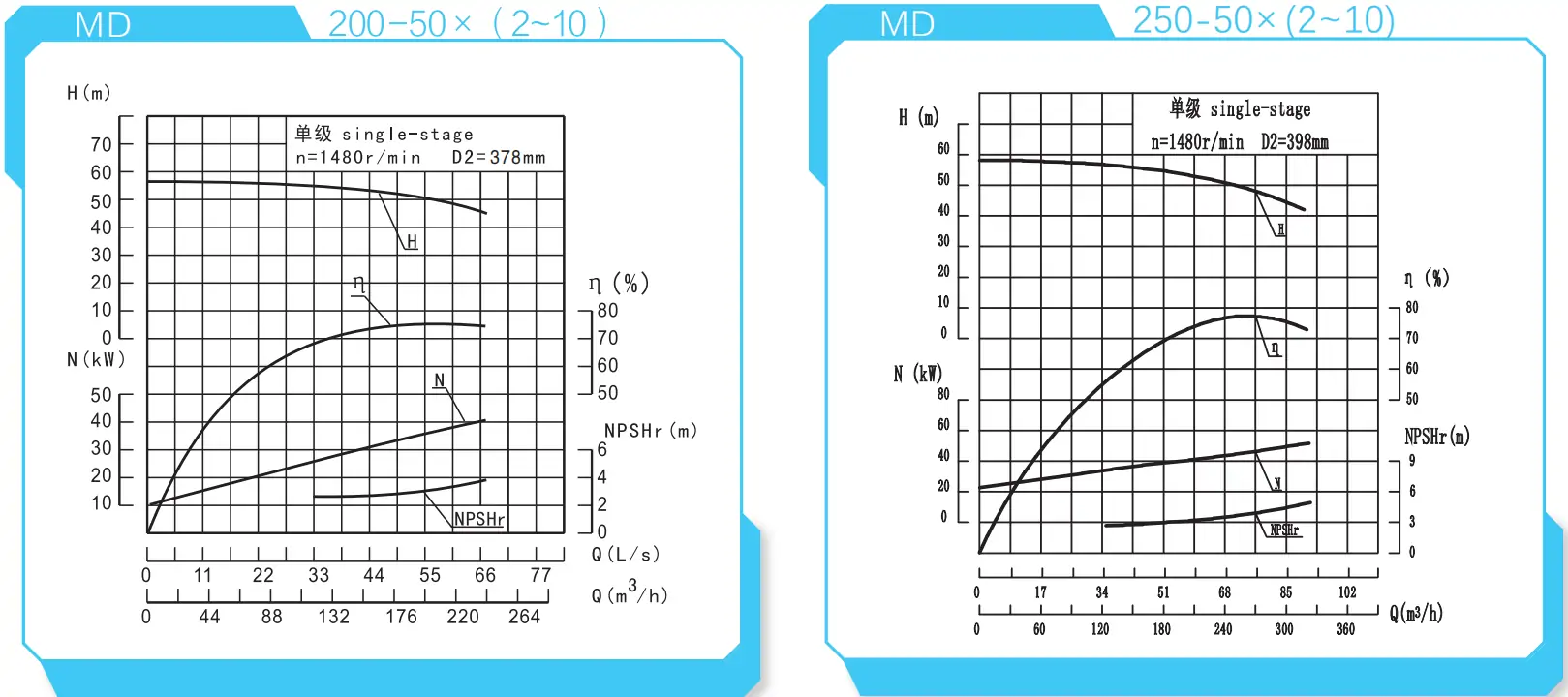
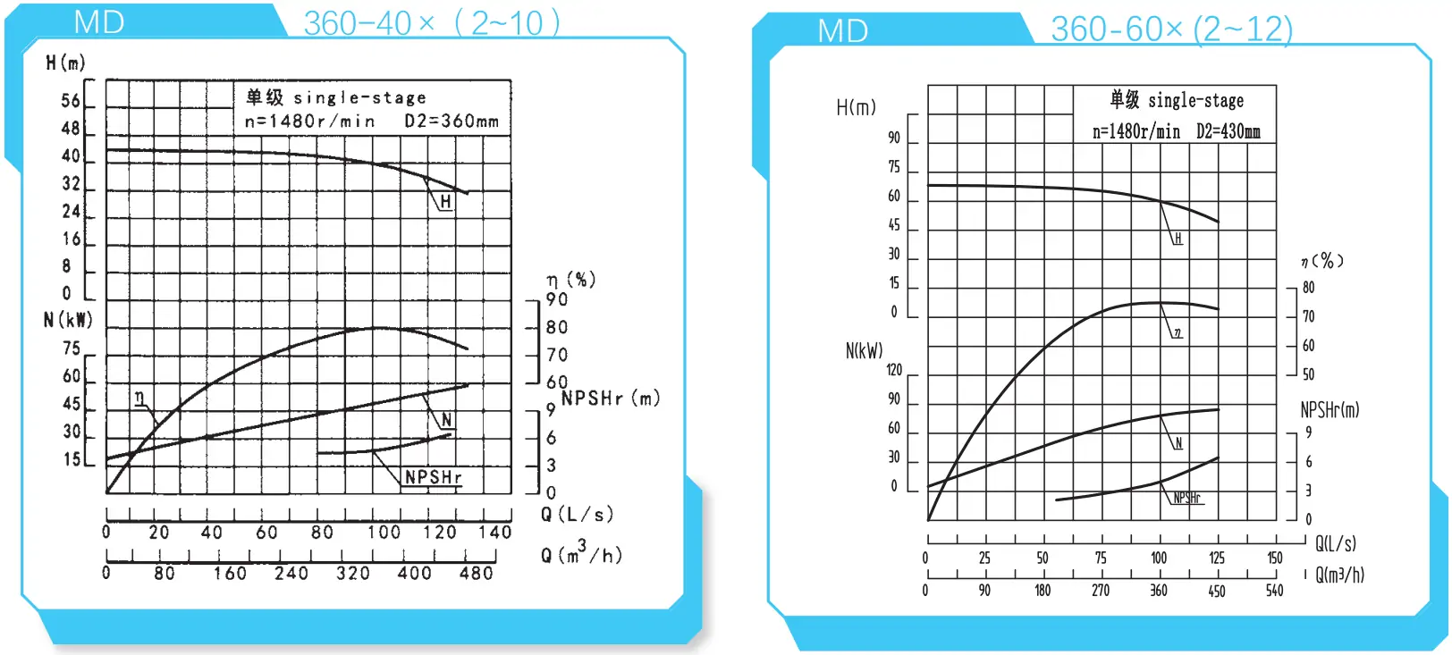
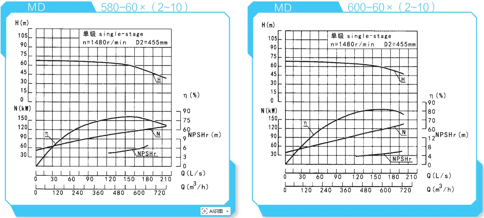
Referencia de la curva de rendimiento
和-MD150-50x-210_1.webp)
_2.webp)
和-MD280-65x-212)_4.webp)
Instalación de una bomba multietapa de alta presión
Al instalar este producto utilizando un sistema de autoequilibrado de tres elementos, además de cumplir con los requisitos generales, se deben tener en cuenta los siguientes puntos:
- 1) Nivele la superficie de cimentación del equipo con un nivel de burbuja. Una vez que el cemento de la cimentación se haya secado, compruebe si la base y los orificios de los pernos de anclaje están flojos.
- 2) Tras montar la unidad de accionamiento, el equipo y la base, compruebe minuciosamente la concentricidad entre el eje de la unidad y el eje de la unidad de accionamiento para asegurarse de que las líneas de ambos ejes coincidan; compruebe también la concentricidad entre el eje principal de la unidad y el eje principal de la unidad de accionamiento para asegurarse de que los centros de ambos ejes estén alineados.
- 3) Durante el montaje de la unidad de accionamiento y el equipo, asegúrese de que el valor de la holgura axial entre las caras de acoplamiento tanto del equipo como de la unidad de accionamiento sea el adecuado.
- 4) Las tuberías de succión y descarga del equipo deben contar con soportes independientes. El equipo solo puede soportar sus propias fuerzas internas y no debe soportar ninguna fuerza externa para evitar daños.
Montaje de equipos
El montaje del equipo suele seguir la secuencia inversa al desmontaje. La calidad del montaje influye directamente en la capacidad operativa, la vida útil y los parámetros de rendimiento del equipo. Preste atención a los siguientes puntos durante el montaje:
- 1) Mantenga la precisión de mecanizado y la rugosidad superficial de los componentes. Evite golpes, rayones u otros daños. Asegúrese de que el sellador utilizado para el sellado esté limpio. Aplique una fuerza uniforme al apretar tornillos y pernos;
- 2) La alineación entre la trayectoria de salida del impulsor de flujo tridimensional y la trayectoria de entrada de los álabes guía queda garantizada por las dimensiones axiales de cada componente. La calidad de la alineación de las trayectorias de flujo afecta directamente al rendimiento del equipo; por lo tanto, las dimensiones del equipo no deben modificarse de manera arbitraria;
- 3) Tras el montaje, gire manualmente el rotor de la bomba para comprobar que gira con suavidad dentro de la carcasa de la bomba y que su posición axial cumple con los requisitos especificados.
Si tiene alguna otra duda técnica relacionada con la instalación, póngase en contacto con nuestro equipo.
Correo electrónico: [email protected]
Teléfono: +86-13651913727
Posibles fallos y sus soluciones
| Síntoma de la falla | Análisis de causas | Solución |
|---|---|---|
| No se produce el cebado; las agujas del manómetro y del vacuómetro oscilan violentamente | Cantidad insuficiente de agua de cebado; fuga de aire en las tuberías o en las conexiones de los manómetros. | Llene con agua de cebado suficiente; purgue el aire por completo; revise las conexiones y juntas de los manómetros; apriete o repare los puntos con fugas. |
| La bomba no se ceba; el vacuómetro indica un alto nivel de vacío | La válvula de pie no se abre o está obstruida; hay una resistencia excesiva en el tubo de succión; la altura de succión es demasiado elevada. | Ajuste y limpie la válvula de pie; limpie o sustituya el tubo de succión; reduzca la altura de succión. |
| El manómetro indica presión, pero no sale agua | Resistencia excesiva en la tubería de descarga; sentido de giro incorrecto; conductos del impulsor obstruidos o dañados; velocidad insuficiente de la bomba. | Revise o acorte la tubería de descarga; limpie los conductos del impulsor o sustituya el impulsor; revise el motor y aumente la velocidad de la bomba. |
| Caudal inferior al requerido en el diseño | Obstrucción de la bomba o de la tubería; desgaste excesivo del anillo de sellado; velocidad insuficiente. | Comprueba si hay obstrucciones en el paso del flujo, limpia la bomba y la tubería; reemplaza el anillo de sellado; aumenta la velocidad de la bomba. |
| Consumo excesivo de energía, interrupción del suministro de agua de compensación, sobrecalentamiento de la cámara de compensación, aumento de la potencia del motor | Fricción entre el rotor y el estator en la bomba; desgaste del impulsor; desgaste en el sistema de autoequilibrado; caudal excesivo de la bomba. | Compruebe si el eje está doblado; inspeccione las zonas de fricción y sustituya el impulsor; repare o sustituya los componentes de autoequilibrado; reduzca el caudal. |
| Ruido anormal dentro de la bomba, no sale agua | Resistencia excesiva en la tubería de succión; válvula demasiado abierta; entrada de aire en el lado de succión que provoca cavitación; temperatura del líquido demasiado alta; rotor desequilibrado, eje doblado o desalineación entre el eje de la bomba y el del motor; cimientos débiles. | Inspeccione el tubo de succión y la válvula de pie; cierre parcialmente la válvula para reducir el caudal; reduzca la altura de instalación; simplifique la tubería de entrada para reducir las pérdidas; selle las fugas de aire; reduzca la temperatura del líquido; apriete los componentes sueltos; equilibre el impulsor mediante mecanizado; alinee la bomba y el motor; refuerce los cimientos. |
| Vibraciones del sistema, sobrecalentamiento de los cojinetes | Desalineación entre el motor y la bomba; lubricación insuficiente o desgaste de los cojinetes; presencia de cavitación. | Alinee los ejes del motor y de la bomba; lubrique o sustituya los cojinetes; reduzca el caudal. |
Nota: Esta tabla de análisis de fallas se aplica específicamente a los sistemas de bombas multietapa de alta presión. Consulte siempre el manual oficial de operación y mantenimiento antes de realizar cualquier tarea de mantenimiento o ajuste.
Ventajas de la bomba multietapa de alta presión
Características técnicas
Estructura optimizada para aplicaciones multietapa de alta altura de elevación, con un control estable de la fuerza axial y una alta fiabilidad operativa a largo plazo.
Alta eficiencia y ahorro energético
Los componentes de paso directo, fabricados mediante fundición de precisión, garantizan unas dimensiones uniformes del recorrido del flujo, lo que proporciona una eficiencia medida un 21 % superior a la de las bombas multietapa convencionales.
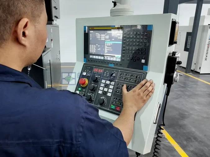
Equipos de fabricación avanzada
Los rotores críticos se someten a una inspección por etapas y a un equilibrado dinámico según las normas G2.5, lo que garantiza un funcionamiento con bajas vibraciones y bajo nivel de ruido.
Selección de materiales
La configuración del material con múltiples gradientes logra un equilibrio entre la resistencia al desgaste, la resistencia a la corrosión y el costo, adaptándose a las diversas condiciones de los túneles y las minas.
Configuración de los materiales del sistema de equilibrado
Los componentes de equilibrado están fabricados con aleaciones con alto contenido de cromo y materiales endurecidos al vacío, lo que les confiere una vida útil significativamente más larga en comparación con las configuraciones estándar.
Principio del sistema de autoequilibrio
El ajuste automático de la fuerza axial minimiza el movimiento y el desgaste del rotor, lo que permite mantener una eficiencia estable y un aumento moderado de la temperatura de los cojinetes.
Solicitud
La bomba multietapa de alta presión cuenta con una estructura de equilibrio tipo tambor. Este diseño de equilibrio tipo tambor utiliza nuevas técnicas de procesamiento de materiales para eliminar los puntos débiles habituales de las bombas multietapa convencionales, como los altos índices de desgaste y la necesidad de un mantenimiento frecuente.
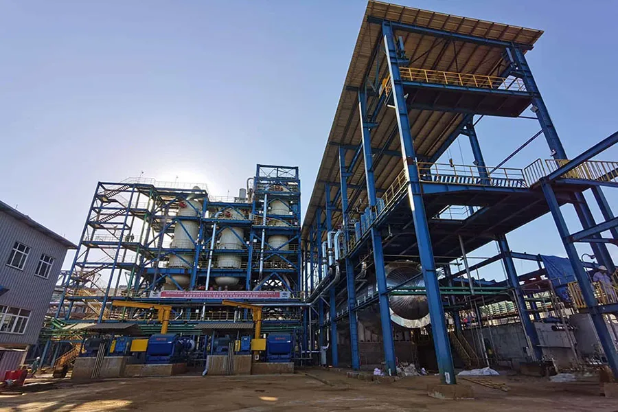
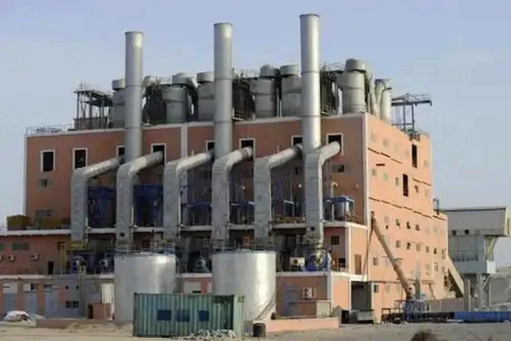
Este producto se utiliza ampliamente en aplicaciones complejas, entre las que se incluyen la desalinización de agua de mar, la extracción de salmuera, el procesamiento químico de la sal, los sistemas de agua de alimentación de calderas, el drenaje con baja cavitación, el transporte de petróleo crudo en yacimientos petrolíferos, las operaciones con escudos de tunelización en medios con alto contenido de sedimentos y el drenaje de minas subterráneas.

Construcción de túneles e ingeniería subterránea
Adecuada para el drenaje de pozos mineros profundos y operaciones mineras; capaz de soportar condiciones de funcionamiento a largo plazo con gran altura de elevación y cargas elevadas.
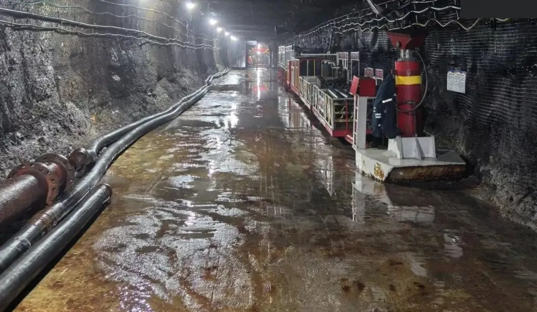
Minería y drenaje de minas
Adecuada para el drenaje de pozos mineros profundos y operaciones mineras; capaz de soportar condiciones de funcionamiento a largo plazo con gran altura de elevación y cargas elevadas.
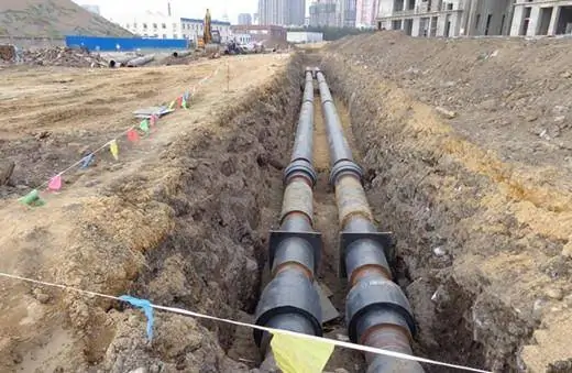
Abastecimiento de agua y alcantarillado municipal e industrial
Se utiliza para el suministro de agua en edificios de gran altura, el transporte de agua a larga distancia y el agua de reposición en sistemas industriales. Se caracteriza por un funcionamiento estable y bajos costos de mantenimiento.
Fabricante profesional de bombas multietapa de alta presión en China
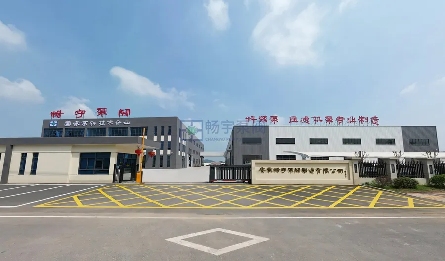
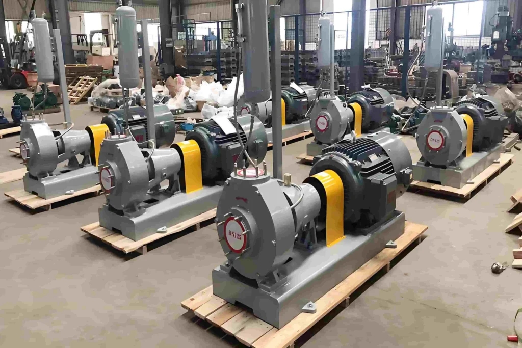
Changyu Pump Industry cuenta con más de 22 años de experiencia en el diseño y la fabricación de bombas centrífugas multietapa, y se especializa en soluciones de bombeo confiables para aplicaciones industriales exigentes. Gracias a nuestras modernas instalaciones de producción, un equipo de ingeniería con amplia experiencia y estrictos sistemas de control de calidad, ofrecemos bombas diseñadas para un alto alcance de elevación, funcionamiento continuo y una larga vida útil.
Nuestro bombas multietapa de alta presión están diseñadas para la construcción de túneles, el drenaje de minas, el suministro de agua industrial y aplicaciones en edificios de gran altura, donde el rendimiento estable, el uso eficiente de la energía y el control preciso de la fuerza axial son fundamentales. Gracias a sus diseños hidráulicos optimizados, materiales robustos y sistemas de equilibrado avanzados, las bombas Changyu garantizan un funcionamiento seguro, eficiente y duradero en condiciones de trabajo extremas.
Contáctenos hoy mismo para obtener un presupuesto personalizado o asistencia técnica profesional: nuestros ingenieros están listos para ayudarle a elegir la bomba adecuada para su proyecto.
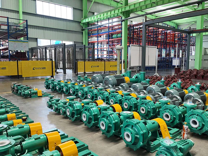
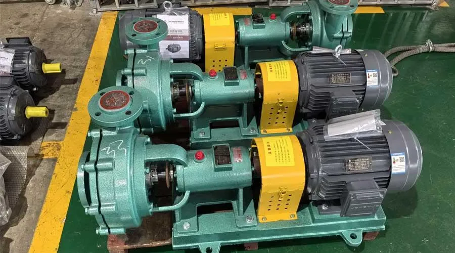
Exposición de fábrica


Preguntas frecuentes

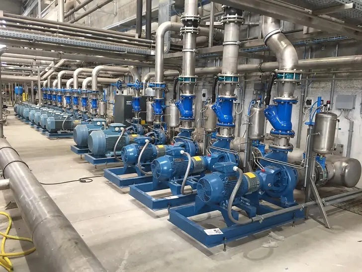
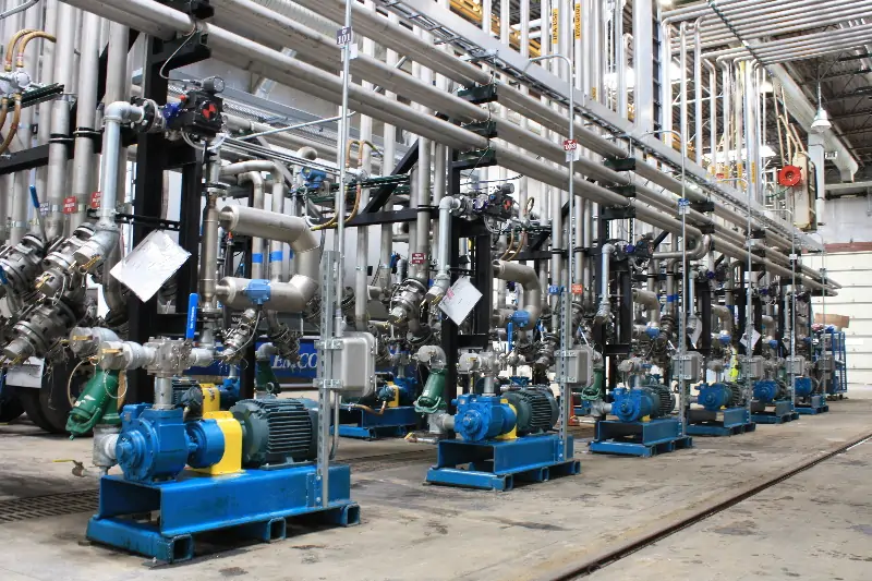
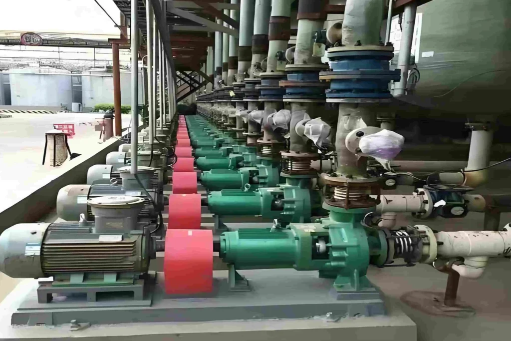
Proyectos

Solicite un presupuesto gratuito
Por favor, rellene los datos del líquido que va a bombear, incluyendo el caudal, la altura, la gravedad específica y la temperatura, para que podamos recomendarle la bomba más adecuada y ofrecerle un presupuesto preciso.