What is Cavitation?
When a liquid at a certain temperature has its pressure reduced to the vaporization pressure corresponding to that temperature, the liquid will produce bubbles. This phenomenon of bubble formation is Cavitation in a pump.
How Cavitation Occurs in Centrifugal Pump?
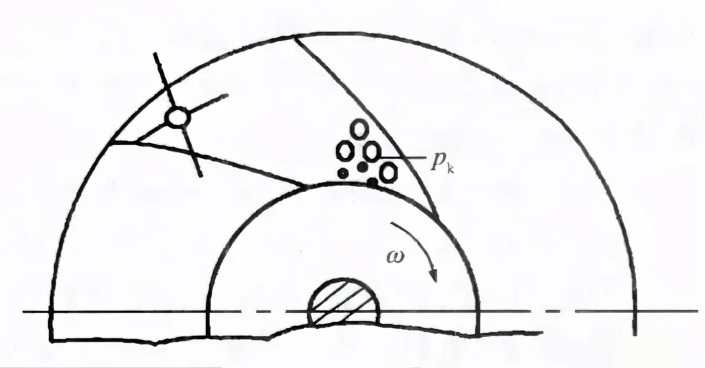
During the operation of a centrifugal pump, if a local area of its flow passage components (usually a certain position slightly behind the inlet of the impeller blade), for some reason, the absolute pressure of the pumped liquid drops to the vaporization pressure at the current temperature, the liquid will begin to vaporize at that location, producing vapor and forming bubbles.
These bubbles move forward with the liquid flow. When they reach a certain high-pressure area, the high-pressure liquid surrounding the bubbles causes them to shrink rapidly until they collapse. At the moment of bubble collapse, liquid particles fill the cavity at high speed and collide with each other, forming a hydraulic shock. When this phenomenon occurs on a solid wall, it causes erosion and damage to the flow passage components.
This process is the cavitation process of a centrifugal pump.
Trigger Conditions of Cavitation
The fundamental cause of cavitation is that the local pressure is lower than the saturated vapor pressure of the liquid.
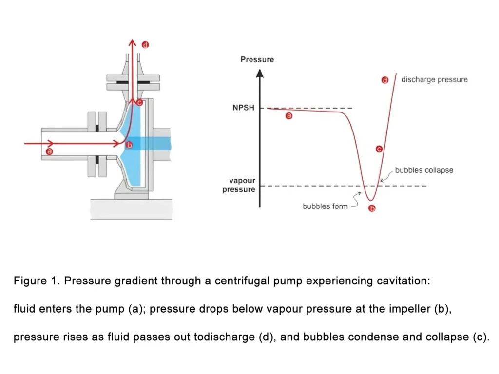
During the operation of a centrifugal pump, the liquid enters the impeller from the suction pipe, and its pressure change follows the following pattern:
Pressure drop at the inlet:
During the process from the storage tank to the pump inlet, due to pipeline resistance and the increase of flow velocity (the increase of kinetic energy leads to the decrease of static pressure energy), the pressure gradually decreases.
Lowest pressure point inside the impeller:
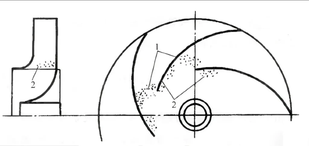
The lowest pressure point usually appears slightly behind the inlet of the impeller blade (about 1/3 of the blade leading edge), where the flow velocity is the highest and the static pressure is the lowest.
Vaporization critical value:
When the pressure at this point drops to the saturated vapor pressure at the current liquid temperature, the liquid begins to vaporize and forms a large number of vapor bubbles.
The Complete Process of Cavitation
Cavitation is a dynamic cycle including bubble generation, development, and collapse.
Bubble Generation Stage
In the low-pressure zone, the liquid vaporizes to produce vapor bubbles. At the same time, gases dissolved in the liquid (such as air) will also be released, forming mixed bubbles. The size of the bubbles ranges from microns to millimeters, and their number increases sharply as the pressure decreases.
Bubble Migration Stage
The bubbles move with the liquid flow into the high-pressure area of the impeller (blade working zone), where the pressure rises rapidly. When the ambient pressure exceeds the vapor pressure, the stability of the bubbles is destroyed.
Bubble Collapse Stage
The bubbles collapse instantaneously under high pressure (within only a few microseconds). The surrounding liquid rushes into the cavity at extremely high speed (which can reach more than 100 m/s), generating a strong hydraulic impact. This process is accompanied by three key effects:
Mechanical impact:
The local pressure can reach tens to hundreds of MPa, equivalent to high-frequency hammering on the metal surface.
Thermal effect:
When the bubbles collapse, the latent heat of vaporization is released, and the local temperature can rise to 200–300°C.
Chemical corrosion:
The high temperature accelerates the oxidation reaction of oxygen on the metal surface, forming electrochemical corrosion.
Characteristics of Cavitation Phenomenon
When cavitation occurs, it can be identified by the following phenomena:
- Auditory signal: A “crackling” or “popping” high-frequency noise is emitted inside the pump. In severe cases, it is accompanied by metal impact sounds.
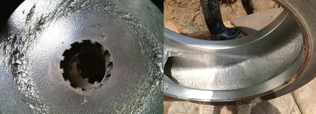
- Visual signal: The impeller surface shows progressive damage from pitting → honeycomb structure → perforation. Typical locations are at the blade inlet edge and the volute tongue.
- Performance changes: The flow rate, head, and efficiency of the pump decrease simultaneously. In severe cases, flow interruption may occur.
Factors Causing Cavitation:
- Installation height: Excessive installation height increases inlet vacuum degree and is the most common cause. Under standard atmospheric pressure, the safe installation height of a clean water pump usually does not exceed 3–5 meters.
- Liquid properties: An increase in temperature (increase in vapor pressure) and higher gas content (increase in bubble nuclei) will significantly reduce cavitation resistance.
- Operating conditions: Deviation from the design flow rate (especially under low-flow conditions) will intensify pressure fluctuations inside the impeller.
- Pump body design: Geometric parameters such as the impeller inlet shape and blade curvature directly affect pressure distribution.
Essential Difference Between Cavitation and Air Binding
It is necessary to distinguish between two easily confused faults:
| Feature | Cavitation | Air Binding |
|---|---|---|
| Root cause | Local pressure < saturated vapor pressure | Air exists inside the pump and vacuum cannot be formed |
| Occurrence stage | Gradually appears during operation | Occurs at startup |
| Typical phenomenon | Noise, vibration, performance decrease, impeller damage | No liquid discharge, no obvious noise |
| Solution | Reduce installation height, increase inlet pressure | Re-prime the pump and exhaust air |
Core Conclusion:
The essence of cavitation is a “boiling–collapse” cycle of liquid in a high-pressure environment. Its destructive effect originates from the synergistic effect of mechanical impact and chemical corrosion.


The key to avoiding cavitation is to ensure that the available Net Positive Suction Head (NPSHa) is greater than the required Net Positive Suction Head (NPSHr), and usually a safety margin of at least 0.3–0.5 m must be guaranteed.
How to Avoid Cavitation in Centrifugal Pump
Improve the structural parameters of the pump inlet
This solution is suitable for Changyu Pump during the design and manufacturing stages of centrifugal pumps. This method is rarely adopted at the production site.
Install an inducer at the pump suction inlet
Installing an inducer has a significant effect on improving the cavitation resistance performance of a centrifugal pump and solving cavitation problems.
Moreover, its structure is simple, easy to manufacture and install, convenient for operation and maintenance, and low in cost. It can be installed and commissioned under the technical guidance of Changyu Pump without affecting production, and is especially suitable for promotion and application at production sites.
Reasonably design the suction pipeline and adjust the installation height
Although this method can eliminate cavitation problems, it is rarely adopted at production sites.
This is because adjusting the suction pipeline and installation height of the pump involves a large amount of engineering work and high construction costs, and is restricted by the construction environment. It can only be carried out during a plant shutdown or a major overhaul.
At the same time, due to process condition limitations, adjusting the suction pipeline and installation height will affect subsequent processes and have a chain reaction.
Optimize process operating conditions
When process conditions allow, changing operating parameters such as pump flow rate, head, rotational speed, and medium operating temperature can avoid the occurrence of cavitation.
Conclusion:
Through the above article, we understand how cavitation occurs in centrifugal pump, as well as how to avoid cavitation in centrifugal pump.
If you want to consider reducing cavitation from the root cause, you can contact us. We will customize the centrifugal pump design according to your specific working conditions to meet your pumping requirements.


If cavitation has already occurred under your current working conditions, you can also contact Changyu Pump now. We have more than 20 years of manufacturing and R&D experience to help you solve pumping problems.
Email: jade@changyupump.com
Phone: +86-13651913727