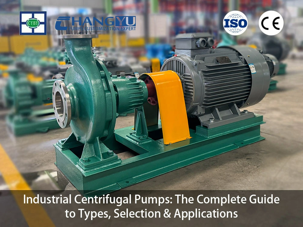
Introduction
Industrial centrifugal pumps are among the most widely deployed fluid-moving machines in the world. From municipal water treatment plants and power generation stations to chemical reactors and mining operations, these pumps form the backbone of modern industrial fluid handling. The global centrifugal pump market, valued at USD 43.29 billion in 2025, is projected to reach USD 58.94 billion by 2030 at a compound annual growth rate of 6.4%—a trajectory driven by expanding industrialization, growing water and wastewater treatment needs, and rising demand for energy-efficient pumping solutions.
This guide provides a structured reference covering the essential knowledge engineers, procurement specialists, and plant operators need to specify, operate, and maintain industrial centrifugal pumps effectively. From the physics of how an impeller generates flow to the practical steps of reading a performance curve, diagnosing cavitation, and selecting materials for aggressive chemicals, this guide aims to be the single resource that consolidates what the current literature offers only in fragments. Drawing on over two decades of experience engineering pumps for demanding industrial applications, Changyu Pump brings verified expertise in corrosion-resistant and wear-resistant centrifugal pump design. Contact us with your process parameters for a specific recommendation.
What Is an Industrial Centrifugal Pump?
An industrial centrifugal pump is a rotodynamic machine that uses a rotating impeller to convert mechanical energy from a driver (typically an electric motor) into kinetic energy in the fluid, which is then converted to pressure energy in the pump casing. This continuous, pulse-free delivery principle makes centrifugal pumps fundamentally different from positive displacement pumps, where flow rate is largely independent of system pressure.
In the broader classification of industrial pumps, centrifugal pumps occupy the rotodynamic category—machines that add energy to the fluid continuously through a rotating element. This distinguishes them from reciprocating pumps (piston, diaphragm) and rotary positive displacement pumps (gear, screw, progressive cavity), which trap and displace discrete volumes of fluid.
Key Components
- Impeller: The rotating heart of the pump. Impeller geometry—closed, semi-open, or open—determines the pump’s solids-handling capability and hydraulic efficiency. Closed impellers, with shrouds on both sides of the vanes, deliver the highest efficiency (typically 70–90%) for clean fluids. Semi-open impellers balance efficiency with anti-clogging performance for medium-concentration slurries. Open impellers provide maximum solids passage at lower efficiency (50–70%).
- Casing (Volute or Diffuser): The stationary housing surrounding the impeller. A volute casing features a spiral-shaped channel that gradually increases in cross-sectional area, converting the fluid’s velocity into pressure. Diffuser casings use a ring of stationary guide vanes around the impeller to achieve the same conversion with higher efficiency in multistage designs.
- Shaft and Bearings: The shaft transmits torque from the driver to the impeller. Radial and thrust bearings support the rotating assembly, absorbing hydraulic loads. Bearing selection—grease-lubricated ball bearings, oil-lubricated sleeve bearings, or product-lubricated designs—depends on operating speed, load, and service environment.
- Sealing System: The shaft seal prevents pumped fluid from leaking along the shaft where it exits the casing. Options include gland packing (low cost, controlled leakage), single mechanical seals (industry standard for most applications), double mechanical seals with barrier fluid (hazardous or high-temperature service), and sealless designs such as magnetic drive pumps, which eliminate the mechanical seal entirely.
Design and Manufacturing Standards
Industrial centrifugal pumps are manufactured to international standards that ensure dimensional interchangeability, performance consistency, and reliability. The two most widely referenced standards are ISO 5199 / ISO 2858 and ANSI/ASME B73.1. Both standards cover horizontal end-suction centrifugal pumps with back pull-out construction, enabling maintenance without disturbing the pump casing or connected pipework.
The performance requirements differ between the standards. ISO 5199 specifies a minimum NPSH margin of 0.5 meters (or greater for fluids near their boiling point) and a hydrotest pressure of 150% of maximum allowable working pressure. ANSI B73.1 specifies a minimum NPSH margin greater than 0.9 meters and defines 27 standard pump sizes. For heavy-duty oil and gas, chemical, petrochemical, and refinery applications, API 610 provides a more stringent standard covering materials, testing, dynamics, and auxiliary systems. API 610 pumps feature centerline mounting for thermal stability—a critical design feature that manages casing expansion and maintains shaft alignment at elevated temperatures. They also incorporate heavy-wall casings for pressure containment and more conservative design margins than ISO or ANSI pumps.
How Does an Industrial Centrifugal Pump Work? Working Principle Explained
Before a centrifugal pump can operate, the pump casing and suction line must be completely filled with liquid—a critical step known as priming. A centrifugal pump cannot generate sufficient pressure to pump air, which is approximately 800 times less dense than water. Once primed, the pump moves fluid through three sequential phases, each corresponding to a specific energy conversion.
- Acceleration: The electric motor drives the impeller. The curved vanes impart a tangential velocity to the fluid. Under the influence of centrifugal force, the fluid accelerates radially outward from the impeller eye to the impeller periphery. In this phase, mechanical shaft power is converted to kinetic energy of the fluid.
- Pressure Build-Up: The fluid exits the impeller at high velocity and enters the volute casing—a spiral-shaped channel of gradually increasing cross-sectional area. As the flow area expands, fluid velocity decreases. By the principle of conservation of energy, this velocity reduction converts kinetic energy into pressure energy—the head that the pump delivers to the system.
- Discharge and Continuous Suction: The pressure differential drives the fluid into the discharge piping. Simultaneously, fluid leaving the impeller eye creates a low-pressure zone that draws fresh fluid in through the suction line, sustaining continuous flow for as long as the impeller rotates.
A special category—self-priming centrifugal pumps—incorporates an internal chamber that retains liquid between cycles, enabling the pump to evacuate air from the suction line automatically and re-prime without manual intervention.
The Pump Performance Curve
The pump performance curve is a graphical representation of the relationship between flow rate (Q) and developed head (H). The characteristic curve of a centrifugal pump shows a declining head as flow increases: at low flow rates, the pump delivers high head; at high flow rates, the head decreases—a behavior that fundamentally distinguishes centrifugal pumps from positive displacement pumps.
Additional curves plotted on the same graph include the efficiency curve, which identifies the Best Efficiency Point (BEP)—the flow rate at which the pump’s hydraulic efficiency peaks. Operating the pump within 70–120% of BEP minimizes internal hydraulic loads, vibration, and wear, maximizing service life. The power curve shows the absorbed shaft power as a function of flow, and the NPSHr curve indicates the minimum suction pressure required to prevent cavitation.
Key Performance Parameters
Beyond the four core parameters displayed on the pump curve, several additional performance parameters are essential for pump selection and system design:
- Net Positive Suction Head Required (NPSHr): The minimum pressure required at the pump suction to prevent cavitation, as specified by the pump manufacturer. NPSHr is a function of pump design and varies with flow rate.
- Net Positive Suction Head Available (NPSHa): The actual suction pressure at the pump inlet under operating conditions, calculated from system parameters: NPSHa = (Patm − Pvap + Pstatic − hf) × (1/ρg). For reliable operation, NPSHa must exceed NPSHr by a minimum margin of 0.5 meters for ISO-compliant pumps (or greater for fluids near their boiling point), or NPSHa > 1.3 × NPSHR for API and HI-compliant applications.
- Specific Speed (Ns): A dimensionless index that correlates impeller geometry with pump performance at the BEP. Low specific-speed pumps (radial impellers) deliver high head at low flow. High specific-speed pumps (axial impellers) deliver low head at high flow. Specific speed provides a quantitative basis for selecting the appropriate impeller type for a given application. For a more detailed exploration of this parameter, see Affinity laws on Wikipedia.
- Suction Specific Speed (Nss): An indicator of the pump’s NPSHr characteristics. Lower Nss values generally indicate a pump with better suction performance and a wider operating window before cavitation onset.
What Are the Main Types of Industrial Centrifugal Pumps?
Centrifugal pumps are classified by flow path geometry, number of impeller stages, shaft orientation, and casing design. Understanding this classification system is essential for matching pump architecture to application requirements.
Classification by Flow Path
- Radial Flow Pumps: Fluid enters the impeller axially and discharges radially. These pumps develop high head at relatively low flow rates and are the most common configuration in industrial process applications.
- Axial Flow Pumps (Propeller Pumps): Fluid enters and discharges axially with minimal radial component. These pumps deliver very high flow rates at low head—typical of flood control, irrigation, and cooling water circulation.
- Mixed Flow Pumps: Fluid enters axially and discharges at an angle between radial and axial. These pumps provide an intermediate combination of head and flow, often used in large-scale water transfer and circulating water systems.
Classification by Stage Count
- Single-Stage Pumps: One impeller is mounted on the shaft. The total developed head is limited to what a single impeller can generate at the design speed—typically up to approximately 130 meters. Single-stage pumps are the default choice for most industrial transfer, circulation, and utility applications.
- Multistage Pumps: Two or more impellers are mounted in series on a common shaft, with the discharge of each stage feeding the suction of the next. This configuration multiplies the developed head, enabling pressures that a single-stage pump cannot achieve. Multistage pumps serve boiler feedwater, high-pressure cleaning, reverse osmosis feed, and long-distance pipeline transport.
Classification by Shaft Orientation
- Horizontal Pumps: The shaft is oriented horizontally, with the pump and driver mounted on a common baseplate. Horizontal configuration simplifies maintenance access and is the most common arrangement for process pumps, utility pumps, and slurry pumps.
- Vertical Pumps: The shaft is oriented vertically, with the driver mounted above the pump. Vertical designs minimize footprint and are specified for sump drainage, deep-well pumping, and applications where the pump must be submerged or where floor space is constrained.
Industrial Centrifugal Pump Types at a Glance
| Pump Type | Flow Path | Stage Count | Key Features | Typical Industrial Applications |
|---|---|---|---|---|
| End-Suction (ISO/ANSI) | Radial | Single | Back pull-out for in-line maintenance; wide material availability | Chemical transfer, water supply, general process |
| Self-Priming | Radial | Single | Internal priming chamber; re-primes automatically after suction loss | Tanker unloading, sump drainage, below-grade lift |
| Magnetic Drive | Radial | Single | Sealless containment; zero leakage by design | Toxic, flammable, or high-value chemicals |
| Multistage | Radial | Multiple | Pressure multiplication per stage; high-head capability | Boiler feed, RO membranes, long-distance pipelines |
| Vertical Cantilever | Radial/Mixed | Single | No submerged bearings; tolerates intermittent dry running | Chemical sumps, electroplating tanks, floor drainage |
| Axial Flow | Axial | Single | High flow, low head; propeller-type impeller | Flood control, irrigation, condenser cooling water |
How to Read and Apply Centrifugal Pump Performance Curves
The pump performance curve is the engineering document that defines how a specific centrifugal pump will behave in a given system. Reading it correctly is the difference between a pump that operates reliably for a decade and one that cavitates, vibrates, and wears out within months.
The Four Curves on a Standard Pump Data Sheet
- Head-Capacity Curve (H-Q): The primary performance curve showing developed head as a function of flow rate. The curve typically slopes downward from a shut-off head (zero flow) to a maximum flow at minimum head.
- Efficiency Curve (η-Q): A bell-shaped curve showing pump efficiency as a function of flow, peaking at the Best Efficiency Point (BEP). The recommended operating region is typically 70–120% of BEP flow for most industrial pumps.
- Power Curve (P-Q): Absorbed shaft power as a function of flow. For radial-flow pumps, power increases with flow—a critical consideration for motor sizing.
- NPSHr Curve: The minimum suction pressure required to prevent cavitation. NPSHr increases with flow, and the operating flow must be limited so that NPSHa exceeds NPSHr by the required margin.
Viscosity Correction
The pump performance curve is developed from tests using water. When the pumped fluid has a viscosity significantly higher than water (above approximately 20 cP), the pump’s head, flow, and efficiency all decrease while the required power increases. The Hydraulic Institute publishes viscosity correction factors in the ANSI/HI 9.6.7-2010 standard, which must be applied to the water-based performance curve to predict pump behavior with viscous fluids accurately.
How to Select the Right Industrial Centrifugal Pump: A 6-Step Framework
Step 1: Characterize the Fluid Properties
Document the fluid’s chemical composition, concentration, pH, temperature (including any process excursions), specific gravity, viscosity, vapor pressure, and solids content (particle size, concentration, hardness). The fluid identity—not a generic label—determines material compatibility, hydraulic performance corrections, and seal selection.
Step 2: Define Flow Rate and Total Dynamic Head
Calculate the required flow rate and total dynamic head (TDH), accounting for static lift, friction losses through the entire piping system (including bends, valves, and fittings), velocity head at the discharge point, and any destination pressure. For clean water and similar fluids, a flow margin of 10–20% accommodates operational fluctuations.
Step 3: Verify NPSH Margin
For all centrifugal pump applications, ensure the available NPSH (NPSHa) exceeds the pump’s required NPSH (NPSHr) by a minimum margin of 0.5 meters for ISO-compliant pumps (or greater for fluids near their boiling point), or NPSHa > 1.3 × NPSHR for API and HI-compliant applications. For fluids within 20°C of their boiling point, recalculate NPSHa using the vapor pressure at the maximum expected operating temperature—a temperature rise of 10°C can substantially reduce NPSHa.
Step 4: Select Pump Type and Materials
Match the pump type to the flow and pressure requirements, installation constraints, and fluid characteristics. Select wetted materials—casing, impeller, shaft sleeve, O‑rings, and gaskets—based on verified chemical compatibility with the specific fluid at its maximum operating temperature.
Step 5: Match the Sealing System
Select the shaft seal based on the fluid’s hazard classification and the required containment level:
- For non-hazardous, moderate-temperature applications: Single mechanical seals are the industry standard, providing cost-effective, reliable containment.
- For hazardous or high-temperature service: Double mechanical seals with a pressurized barrier fluid (API Plan 53) or a gas barrier (API Plan 74) provide the required additional cooling and containment.
- For toxic, flammable, or high-value fluids: Sealless magnetic drive pumps are the standard specification, achieving zero leakage by design by transmitting torque across a stationary containment shell and eliminating the mechanical seal entirely.
Step 6: Evaluate Total Cost of Ownership
The purchase price of a centrifugal pump typically represents only 15–25% of its lifetime cost. Energy consumption (often 60–70% of lifetime cost), wear part replacement frequency, maintenance labor, and the production cost of unplanned downtime each contribute to the total cost of ownership. Evaluate TCO over a three- to five-year horizon for accurate comparison.
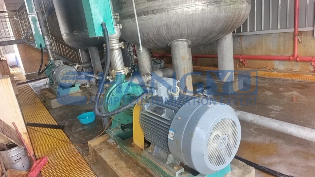
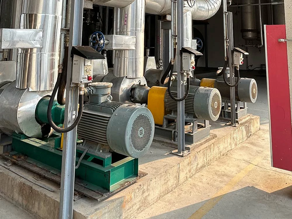
Industrial Centrifugal Pump Applications Across Key Industries
Water and Wastewater Treatment: The largest single application segment for centrifugal pumps. Raw water intake, treatment chemical dosing, filtration feed, high-pressure membrane feed, and treated water distribution all depend on centrifugal pump technology. Wastewater applications demand solids-handling impellers for sludge transfer and grit-laden process streams.
Oil and Gas: Upstream (produced water injection, crude oil transfer), midstream (pipeline booster stations, tank farm transfer), and downstream (refinery process pumps, product loading) applications. Refinery pumps are typically specified to API 610 for high-temperature, high-pressure hydrocarbon service with centerline mounting and heavy-wall casings.
Chemical and Petrochemical Processing: Transfer of acids, alkalis, solvents, and intermediates between storage, reactors, and finishing equipment. Chemical-grade centrifugal pumps are constructed with fluoroplastic linings (PTFE, PFA, FEP), duplex stainless steel, or all-plastic casings matched to the specific chemical at its operating temperature and concentration.
Power Generation: Boiler feedwater (multistage, high-head), condenser cooling water circulation (high-flow axial or mixed-flow), flue gas desulfurization (FGD) slurry recirculation (rubber-lined or duplex stainless), and ash handling. Power plant pumps operate continuously for extended periods, and reliability is the overriding specification criterion.
Mining and Mineral Processing: Mill discharge, hydrocyclone feed, flotation circuit transfer, and tailings disposal demand pumps with wear-resistant wetted components—high-chrome iron, natural rubber, or UHMW-PE linings—capable of handling coarse, angular, highly abrasive solids at high concentrations.
Pulp and Paper: Paper stock and pulp slurry transfer, black liquor circulation, and bleaching chemical handling require pumps with corrosion-resistant wetted components capable of handling fibrous solids and chemically aggressive process streams. Duplex stainless steel and fluoroplastic-lined centrifugal pumps are widely specified for these demanding applications.
Food and Beverage: Hygienic centrifugal pumps for product transfer, CIP (clean-in-place) chemical circulation, and utility services. Stainless steel construction (316L), sanitary mechanical seals, and designs that permit thorough cleaning without disassembly are standard requirements.
Pharmaceutical and Biotechnology: High-purity solvent transfer, API intermediate handling, and sterile process duties require pumps that prevent both leakage and product contamination. Electropolished stainless steel or PTFE/PFA-lined flow paths with sealless magnetic drive are the standard specification.
Common Problems, Causes, and Solutions
Cavitation
Symptoms: Loud noise (often described as “gravel passing through the pump”), vibration, reduced flow and head, pitting damage on impeller surfaces.
Causes: Insufficient NPSHa relative to NPSHr. This occurs when suction pressure is too low due to high static lift, excessive suction piping friction losses, clogged strainers, or operation at a flow rate far above the BEP. Elevated fluid temperature, which increases vapor pressure, also reduces NPSHa. As specified in ISO 5199 and HI standards, a minimum NPSH margin is required for reliable operation.
Solutions: Reduce suction lift height; increase suction pipe diameter to reduce friction losses; clean suction strainers; operate the pump within its recommended flow range; lower the fluid temperature where practical; select a pump with lower NPSHr or a larger impeller eye diameter.
Excessive Vibration
Symptoms: Measurable increase in vibration levels, audible noise, premature bearing and seal failure.
Causes: Misalignment between the pump and driver; unbalanced impeller due to uneven wear or solids accumulation; operation far from BEP, causing hydraulic instability; cavitation; loose foundation bolts; or an inadequate baseplate or foundation.
Solutions: Verify laser alignment between pump and driver; clean and dynamically balance the impeller; operate within 70–120% of BEP; address cavitation root causes; tighten foundation bolts to specified torque; ensure the baseplate is grouted and the foundation is adequate.
Reduced Flow or Head
Symptoms: Pump does not deliver the design flow rate or discharge pressure.
Causes: Worn impeller clearance rings, allowing excessive internal recirculation; clogged impeller passages; air ingress through the suction line or stuffing box; reversed rotation direction; or a closed or partially closed discharge valve.
Solutions: Adjust impeller clearance or replace wear rings; disassemble and clean the impeller; check suction piping for air leaks; verify correct motor rotation; fully open the discharge valve.
Mechanical Seal Leakage
Symptoms: Visible fluid leakage from the seal area; dripping from the stuffing box.
Causes: Worn seal faces due to abrasives in the pumped fluid; chemical attack on seal elastomers; dry running of the seal faces; or inadequate seal flush flow and pressure. In pumps where the bearing frame is close to the seal, prolonged leakage can corrode nearby bearings and components.
Solutions: Install a suction strainer; verify elastomer compatibility with the fluid; ensure the pump is primed before start-up and that the seal flush system is operational; replace the seal with materials matched to the fluid chemistry and temperature. For process pumps with a lantern bracket between the bearing frame and pump casing, any leakage is typically directed downward and away from the bearings, providing an additional measure of protection.
Bearing Overheating
Symptoms: Elevated bearing housing temperature; lubricant discoloration or odor; increased power consumption.
Causes: Over-greasing or under-greasing; lubricant contamination; excessive radial or thrust load from operation far from BEP; misalignment between pump and driver; or inadequate bearing housing cooling for high-temperature service.
Solutions: Follow the manufacturer’s lubrication schedule and quantity; replace contaminated lubricant; operate the pump within its recommended flow range; verify alignment; for high-temperature pumps, ensure the bearing housing cooling jacket is functioning.
Changyu Pump Industrial Centrifugal Pump Solutions
Changyu Pump designs and manufactures a comprehensive range of industrial centrifugal pumps engineered for corrosive, abrasive, and high-temperature applications across chemical processing, mining, water treatment, and general industry.
UHB Series Horizontal Chemical Slurry Pump
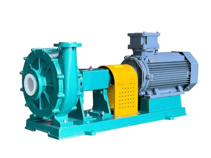
The UHB Series is a horizontal, single-stage, single-suction centrifugal pump specifically developed for conveying corrosive slurries containing fine particles. Its steel-lined UHMW-PE construction combines exceptional wear resistance with broad chemical compatibility, handling sulfuric acid, hydrochloric acid, phosphoric acid, and abrasive media across a wide range of concentrations and temperatures. This means you can deploy a single pump platform for multiple corrosive slurry duties—from phosphoric acid circulation in fertilizer plants to TiO₂ slurry transfer in pigment manufacturing—without the material compatibility concerns that accompany metal pumps. The semi-open impeller ensures high flow capacity without clogging, and the pump is available with mechanical or dynamic seals. The cantilevered, front-opening design enables rapid wet-end inspection and reduces maintenance downtime.
Key Specifications: Flow 3–2,600 m³/h | Head 5–100 m | Power 0.75–300 kW | Speed 750–2,900 r/min | Temperature -20°C to 90°C | Materials: UHMW-PE lining
CYQ Series High Temperature Magnetic Drive Pump
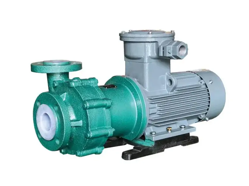
The CYQ Series is a sealless magnetic drive centrifugal pump engineered for high-temperature, corrosive, and hazardous chemical transfer. Advanced magnetic drive technology eliminates the mechanical shaft seal entirely—torque is transmitted across a stationary isolation sleeve, enclosing the process fluid in a fully sealed chamber. Constructed with PFA or FEP fluoroplastic lining, the CYQ Series handles sulfuric acid at any concentration, hydrochloric acid, nitric acid, and aggressive solvents at temperatures from -20°C to 180°C. High-performance rare-earth permanent magnets resist demagnetization at elevated temperatures, and the premium isolation sleeve material—carefully selected for its chemical compatibility and resistance to eddy-current heating—minimizes energy losses while maintaining containment integrity.
Key Specifications: Flow 3–800 m³/h | Head 15–125 m | Power 2.2–110 kW | Speed 2,950 r/min | Temperature -20°C to 180°C | Materials: PFA, FEP, PTFE lining
ZCQ Series Fluorine-Lined Magnetic Self-Priming Pump
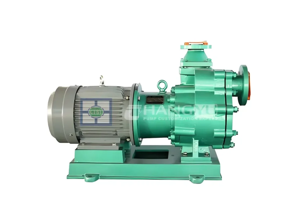
The ZCQ Series merges magnetic drive sealing with self-priming capability in a single pump architecture. The pump casing and impeller are lined with FEP (F46) or PFA, providing verified chemical compatibility for aggressive acids, alkalis, and solvents. The magnetic coupling eliminates the mechanical seal for zero-leakage containment, while the specialized pump cavity design withstands short-term vacuum conditions and intermittent dry running—making it particularly suited to raw material unloading from tankers and drums where the pump must self-prime against suction lift.
Key Specifications: Flow 3–250 m³/h | Head 12.5–50 m | Power 0.75–30 kW | Speed 968–3,450 r/min | Temperature -20°C to 150°C | Materials: FEP (F46), PFA lining
FZB Series Fluoroplastic Self-Priming Centrifugal Pump
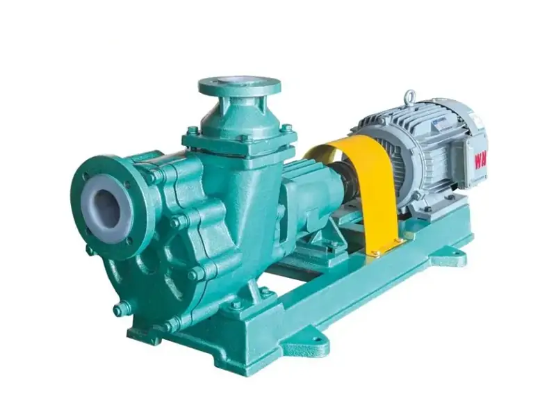
The FZB Series is a new generation of corrosion-resistant self-priming centrifugal pumps developed by Changyu Pump. All flow-through components are lined with FEP (F46) or PFA fluoroplastic, combining the chemical inertness of fluoropolymers with a self-priming hydraulic design capable of lifting fluid up to 5 meters on the suction side—extendable by an additional 1–2 meters with a check valve. The external bellows mechanical seal resists chemical attack and thermal stress. When the liquid level is below 1.5 meters, the FZB Series offers advantages over submersible pumps including lower initial cost, easier maintenance access, longer service life, and lower operating costs.
Key Specifications: Flow 2.5–100 m³/h | Head 15–50 m | Power 0.75–55 kW | Speed 968–3,450 r/min | Temperature -20°C to 150°C | Materials: FEP (F46), PFA lining
Frequently Asked Questions About Industrial Centrifugal Pumps
Q1: What is the difference between a centrifugal pump and a positive displacement pump?
A: The fundamental distinction lies in how each pump type interacts with system pressure. A centrifugal pump uses a rotating impeller to add kinetic energy to the fluid, and its flow rate varies with discharge pressure—at higher pressure, flow decreases. A positive displacement pump traps a fixed volume of fluid and mechanically displaces it, producing flow that is largely independent of system pressure. Centrifugal pumps are preferred for high-flow, low-to-moderate-viscosity applications; positive displacement pumps serve high-viscosity, high-pressure, and metering duties.
Q2: How do I read a centrifugal pump performance curve?
A: The key to interpreting a pump curve is understanding that it represents four interdependent parameters, not independent specifications. A standard pump curve plots four parameters against flow rate: head (H-Q), efficiency (η-Q), power (P-Q), and NPSHr. The head curve shows the pump’s pressure-producing capability. The efficiency curve identifies the Best Efficiency Point (BEP)—the flow rate at which hydraulic efficiency peaks. The pump should be selected so its normal operating point falls within 70–120% of BEP for optimal reliability and service life.
Q3: What causes cavitation in a centrifugal pump and how can it be prevented?
A: Cavitation is a thermodynamic phenomenon, not merely a mechanical problem—it occurs when the pressure at the pump suction falls below the fluid’s vapor pressure, causing vapor bubbles to form and subsequently collapse violently in higher-pressure zones. This damages the impeller, causes noise and vibration, and reduces pump performance. As specified in ISO 5199 and HI standards, prevention requires ensuring that the available NPSH (NPSHa) exceeds the required NPSH (NPSHr) by a minimum margin of 0.5 meters. This can be achieved by reducing suction lift, increasing suction pipe diameter, lowering fluid temperature, or operating within the pump’s recommended flow range.
Q4: What is the Best Efficiency Point (BEP) and why does it matter?
A: The BEP is more than an efficiency metric—it is the operating point at which the pump’s internal hydraulic loads are minimized. At the BEP, the pump achieves its maximum hydraulic efficiency. Operating near the BEP minimizes internal hydraulic loads, vibration, shaft deflection, and bearing loading. Sustained operation far from the BEP—either at very low or very high flow rates—accelerates wear, increases energy consumption, and shortens the pump’s service life.
Q5: What is the difference between ISO 5199 and ANSI B73.1 pump standards?
A: The primary distinction between these standards is dimensional and regional, not functional. As defined by their respective standards bodies, both govern horizontal end-suction centrifugal pumps with back pull-out construction. ISO 5199 is the globally recognized standard (particularly in Europe and Asia), while ANSI/ASME B73.1 is the North American standard. The two standards share the same basic construction but differ in dimensional specifications and some performance requirements. ISO 5199 specifies 34 pump sizes; ASME B73.1 specifies 27 sizes. Both ensure interchangeability and consistent performance across manufacturers.
Q6: How do I select pump materials for corrosive chemicals?
A: Material selection must be verified for the specific chemical at its operating concentration and temperature—there is no universal “corrosion-resistant” material. For hydrochloric acid and sulfuric acid above 15%, non-metallic materials—PP, PVDF, PTFE, or PFA linings—are required. For nitric acid, stainless steel 316L may be suitable at moderate concentrations and temperatures but must be verified. For mixed chemical streams, PTFE- and PFA-lined pumps provide the broadest chemical compatibility. Metals, including stainless steels, are attacked by hydrochloric acid at any concentration through chloride-induced pitting.
Q7: What is the purpose of self-priming capability in a centrifugal pump?
A: Self-priming capability solves a specific installation problem: how to operate a centrifugal pump when it is mounted above the liquid source and cannot rely on gravity-fed flooded suction. A self-priming pump can evacuate air from the suction line and draw fluid into the pump without manual priming. This capability is essential in tanker unloading, sump drainage, and chemical transfer from below-grade tanks. Self-priming designs incorporate an internal reservoir that retains sufficient liquid between cycles to re-prime automatically.
Q8: How do I calculate the total dynamic head for a centrifugal pump system?
A: Total Dynamic Head (TDH) = Static Head (elevation difference between suction and discharge liquid levels) + Friction Head (losses through piping, elbows, valves, and fittings at the design flow rate) + Velocity Head at the discharge point + any Pressure Head required at the destination. For viscous fluids above approximately 20 cP, friction losses must be calculated using the fluid’s actual viscosity at the pumping temperature and applying correction factors per ANSI/HI 9.6.7-2010. A flow margin of 10–20% accommodates operational variations and future system changes.
Expert Recommendations from Changyu Pump Engineers
- Select the pump to operate within 70–120% of its Best Efficiency Point. A pump that operates far from its BEP—even if it satisfies the flow and head requirements on paper—will consume more energy, vibrate excessively, and require more frequent maintenance. The BEP is not a theoretical optimum; it is the engineering point at which internal hydraulic loads are minimized, and the pump’s service life is maximized.
- Verify material compatibility at the maximum operating temperature, not the nominal process temperature. A material that resists a chemical at 25°C can fail rapidly at 85°C. Chemical attack rates can approximately double with every 10°C temperature rise. Confirm every wetted component—casing, impeller, shaft sleeve, O‑rings, gaskets, and seal faces—against the worst-case thermal and chemical condition.
- Do not neglect the suction piping design. More centrifugal pump failures trace back to inadequate suction conditions than to any other single cause. The suction line should be as short and direct as practical, with a diameter at least equal to the pump’s suction flange. Use long-radius elbows rather than short-radius fittings, and install a strainer to protect the pump from debris. For fluids within 20°C of their boiling point, calculate NPSHa at the maximum expected operating temperature—not the nominal temperature.
- For hazardous, toxic, or high-value chemicals, select sealless magnetic drive pumps. Eliminating the mechanical seal removes both a leak path and a routine maintenance item. The higher initial cost of a magnetic drive pump is typically recovered through eliminated seal replacements, reduced flush water consumption, and avoided emissions reporting—often within the first three years of operation.
Conclusion
Industrial centrifugal pumps are not commodity items selected on flow and head specifications alone. Each element of the pump—impeller geometry, casing design, material system, bearing arrangement, and sealing technology—must be matched to the specific fluid, operating conditions, and reliability requirements of the application. The pump that handles clean cooling water for a decade may fail within weeks when exposed to a 60% solids mining slurry or a 98% sulfuric acid stream at 120°C.
The selection process begins with a complete characterization of the fluid and the system, proceeds through pump type and material matching, and concludes with a total cost of ownership evaluation that accounts for energy, wear parts, maintenance labor, and the production cost of unplanned downtime. A pump that operates at its BEP with materials verified for the specific fluid at its maximum temperature will deliver the lowest total cost of ownership and the longest mean time between repairs.
Changyu Pump’s UHB, CYQ, ZCQ, and FZB series centrifugal pumps provide corrosion-resistant, wear-resistant, and sealless pump platforms for demanding industrial fluid handling applications. Contact our engineering team with your process parameters and fluid properties. We will provide a detailed pump recommendation and quotation tailored to your industrial application.