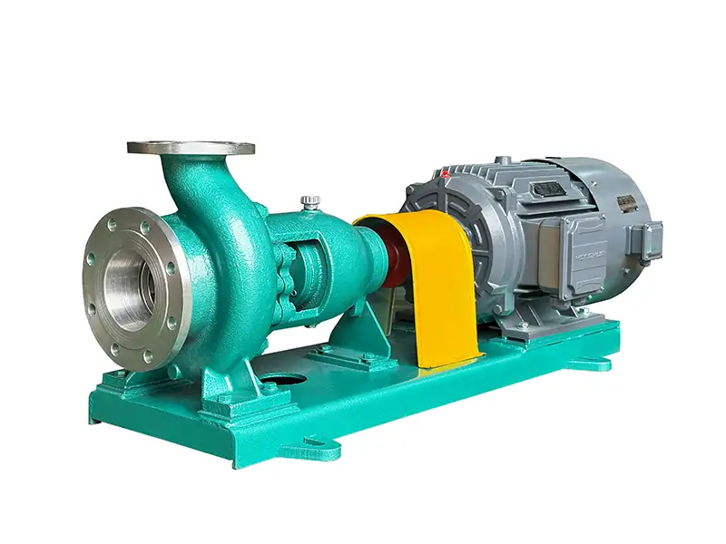
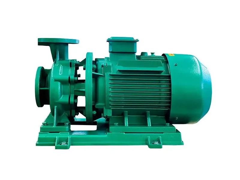
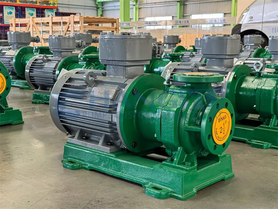
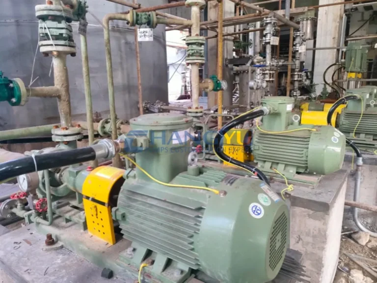
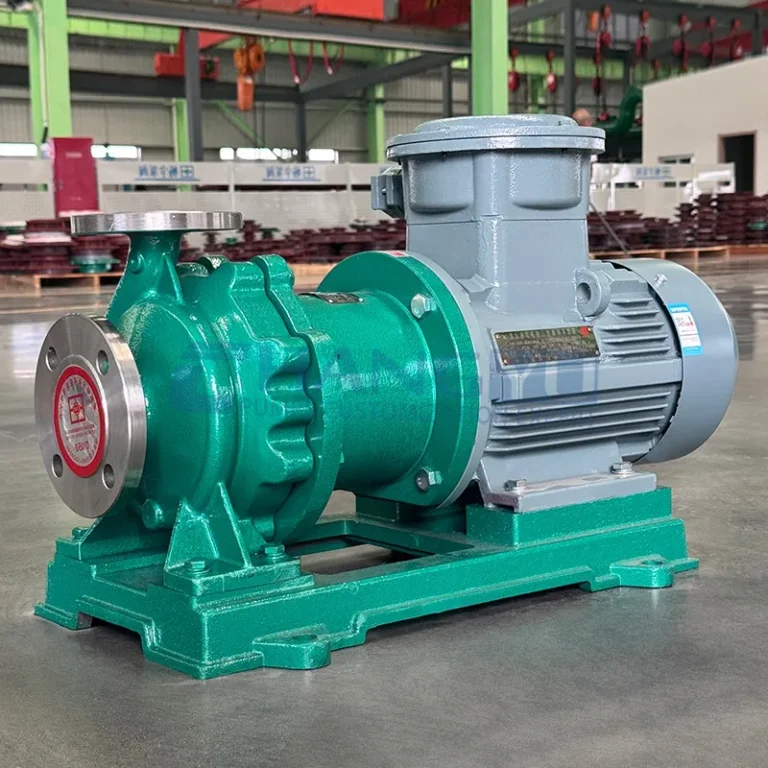
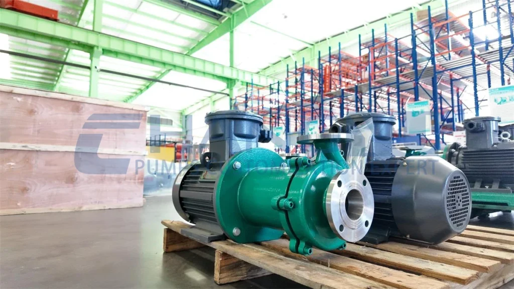
A bomba centrífuga is a type of pump that utilizes the principle of centrifugal force to transport liquids. Its core function is to convert the rotational kinetic energy of an electric motor or engine into fluid energy, thereby generating flow and pressure. In this article, we will take an in-depth look at the centrifugal pump parts and their working principles. We will break down each component and explain its operational process to help you gain a clear and comprehensive understanding of this equipment.
Centrifugal Pump Parts
Although there are many types of centrifugal pumps with different applications, their basic core structures are similar. Understanding these key components will help you understand how centrifugal pumps work. We will provide a detailed introduction to the main core components of centrifugal pumps, including impellers, pump casings, and sealing systems.
Table of Contents

Impulsor
It is one of the core components of a centrifugal pump, primarily responsible for transferring mechanical energy from the motor to the liquid, generating centrifugal force to impart kinetic and potential energy to the liquid.
Types of impellers:
Based on structural form, they are divided into open, semi-open, and closed types. Closed impellers have the highest efficiency and are the most widely used; open and semi-open impellers are suitable for conveying fluids containing solid particles or viscous fluids.

When the centrifugal pump starts, the pump shaft drives the impeller to rotate at high speed, forcing the liquid pre-filled between the blades to rotate. Under the influence of inertial centrifugal force, the liquid moves radially from the center to the outer periphery of the impeller.
The liquid gains energy as it flows through the impeller. When the liquid leaves the impeller and enters the pump casing, it decelerates due to the gradually expanding flow channels inside the casing, converting part of its kinetic energy into static pressure energy, and finally flows tangentially into the discharge pipeline.
Pump casing
The pump casing refers to the spiral-shaped flow channel with gradually increasing cross-sectional area from the impeller outlet to the inlet of the next stage impeller or to the pump outlet pipe. The flow channel gradually widens, converting the fluid’s kinetic energy into static pressure energy, which is then discharged through the pipe.

Main functions:
Collecting high-speed fluid flowing out from the impeller outlet;
Effectively converting the fluid’s kinetic energy into pressure energy;
Smoothly guiding the pressurized fluid to the pump’s discharge piping;
Withstanding the fluid pressure inside the pump.
Types:
Snail-shell type pump casing: The most common type, with a spiral-shaped flow channel cross-section and a simple structure.
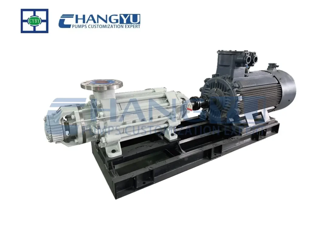
Guide vane pump casing: Features fixed guide vanes mounted around the impeller’s periphery. The guide vanes convert the fluid’s kinetic energy into pressure energy and direct the fluid toward the outlet. Commonly used in multistage pumps or high-pressure pumps.
Pump shaft

Its primary function is to transmit power and support the impeller to maintain normal operation at its working position. Since it must perform additional energy conversion functions, its material must possess sufficient strength, stiffness, and wear resistance. It is typically made of high-strength alloy steel.
The impeller and shaft are connected via a key. Since this connection method can only transmit torque and cannot fix the axial position of the impeller, a shaft sleeve and locking nut are also used in the pump to secure the axial position of the impeller.
Shaft sleeve
The shaft sleeve protects the pump shaft, transforming the friction between the packing and the shaft into friction between the packing and the shaft sleeve. Therefore, the shaft sleeve is a wear-prone component in centrifugal pumps.

The surface of the shaft sleeve can typically be treated using methods such as carburizing, nitriding, chrome plating, or coating. The surface roughness requirement generally needs to reach Ra3.2 μm to Ra0.8 μm. This reduces the friction coefficient and extends the service life.
Skeleton oil seal
A skeleton oil seal is one of the most common and widely used types of seals for rotating shafts, commonly known as oil seals. Its primary function is to seal lubricating oil (or grease) within mechanical equipment while preventing external contaminants such as dust and mud from entering the system.

Mechanical Seal
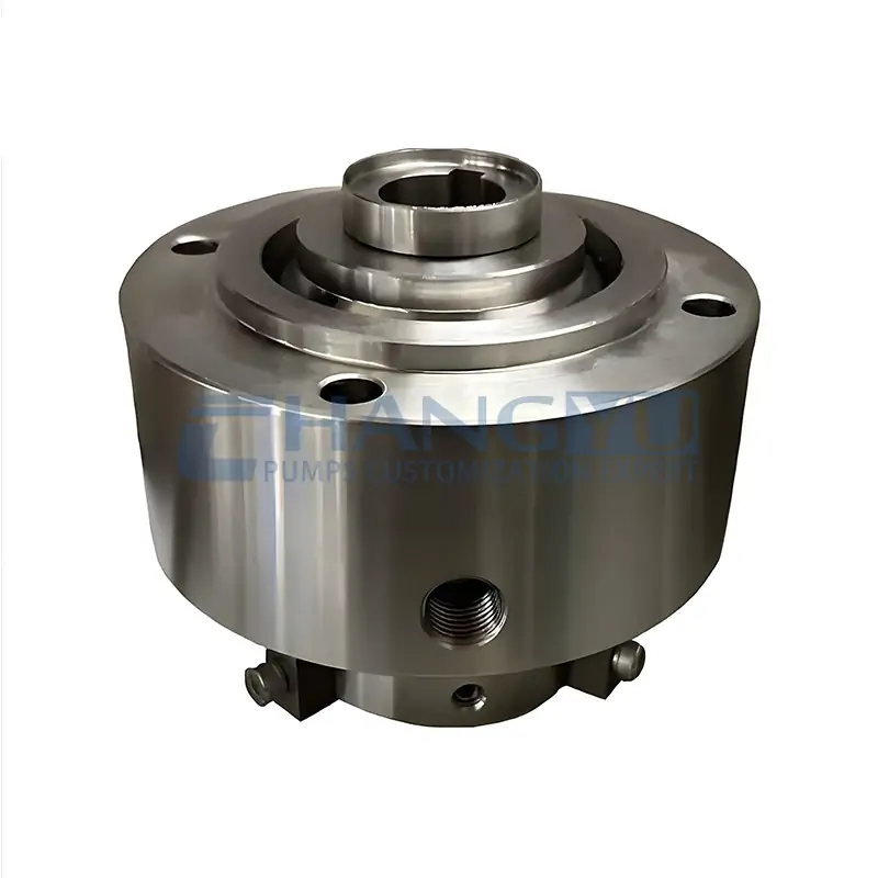
Single Mechanical Seal (Single-End Face Seal)
Single mechanical seals are suitable for conveying viscous liquids under general operating conditions, such as applications with moderate viscosity, low pressure, and moderate temperature.
They feature a simple structure, lower cost, and convenient installation and maintenance. However, their sealing performance is slightly inferior to that of double mechanical seals.
They are suitable for media with good self-lubricating properties and in applications where minor leakage is acceptable.
They are not suitable for toxic, flammable, explosive media or applications with strict leakage control requirements.
Double Mechanical Seal (Double-End Face Seal)
Double mechanical seals are suitable for high-pressure, high-temperature, highly corrosive media, as well as fluids containing suspended particles or fibers, and flammable or explosive media.
- Nominal pressure: ≤ 1 MPa
- Working temperature range: -20°C to 200°C
They are particularly suitable for flammable, explosive, toxic, particle-containing, or poorly lubricating media.
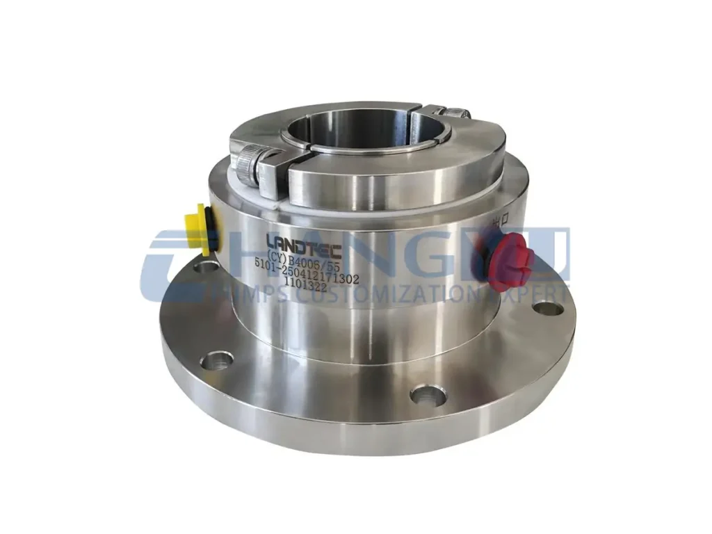
Widely used in chemical, pharmaceutical, and other industries requiring high-performance sealing. When sealing high-pressure media, the pressure differential across each sealing face can be reasonably distributed, thereby increasing the allowable working pressure range.
In addition, they are suitable for shaft sealing in glass-lined mixing vessels and glass-lined reactors. They can handle various strongly corrosive and particle-containing media and are typically used in conjunction with hydraulic pump stations.
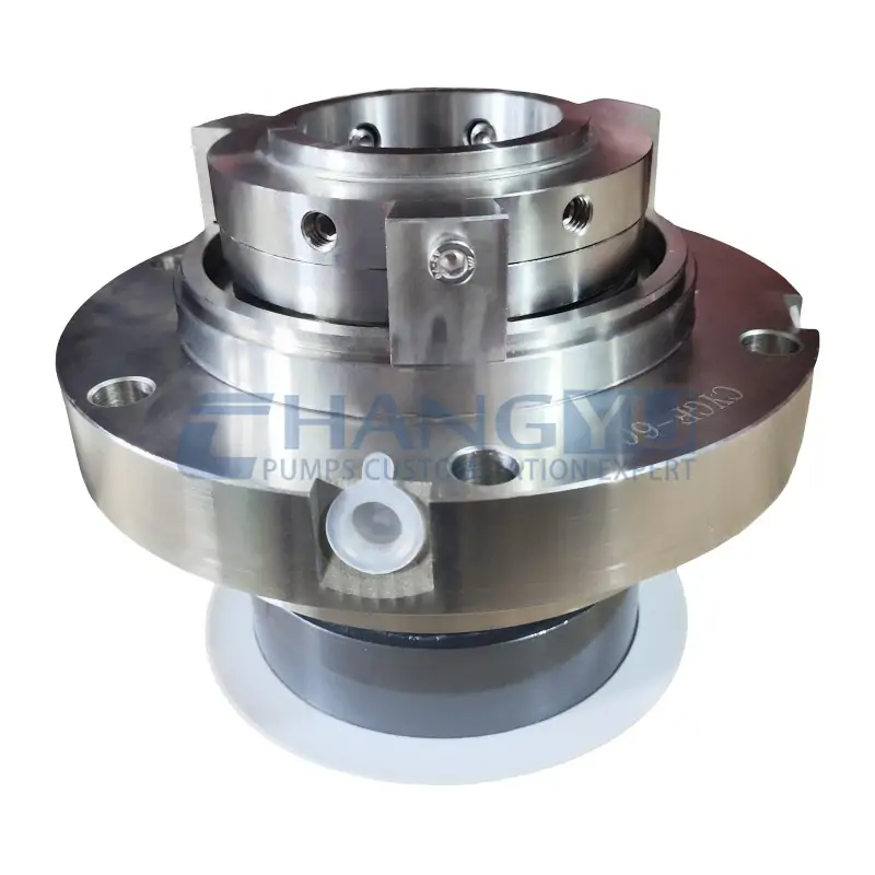
Cartridge Mechanical Seal
Cartridge mechanical seals are designed for severe operating conditions such as high speed, high precision, high temperature, and high pressure.
They are commonly used in high-speed pumps, compressors, and mixers, meeting the demanding sealing performance requirements of rotating equipment.
They provide excellent performance under various harsh operating conditions.
Centrifugal Pump Working Principle
The working principle of a centrifugal pump involves the impeller’s high-speed rotation, which imparts kinetic energy to the liquid under the influence of centrifugal force and converts it into pressure energy, thereby achieving fluid conveyance. Before startup, the pump housing and suction piping must be filled with the medium to prevent cavitation.
During operation, the rotating impeller accelerates the liquid and flings it toward the outer edge, while a low-pressure zone forms at the impeller center, continuously drawing in liquid and conveying it to the outlet. Through continuous cyclic operation, a steady and continuous conveying process is achieved.
Conclusão
Through the above content, we believe you now have a good understanding of centrifugal pump parts and how they work. If you have any further questions or technical issues regarding this equipment, please feel free to contact the Changyu technical team at any time. We will respond quickly within 24 hours and address your concerns.
Correio eletrónico: jade@changyupump.com
Phone: +86-13651913727