
Khi chúng ta thảo luận về máy bơm mắc song song so với mắc nối tiếp với khách hàng tại Bơm ChangYu, chúng ta bắt đầu từ hệ thống đường ống và nhiệm vụ mới. Hai máy bơm có thể tăng thêm công suất, nhưng mua thêm một tổ máy không đảm bảo gấp đôi lưu lượng đầu ra. Chúng tôi đã chứng kiến khách hàng mua máy bơm trước rồi mới xem xét lại đường ống sau. Đến lúc đó, việc chỉnh sửa bố trí tốn kém hơn so với việc kiểm tra đường cong hệ thống ngay từ đầu.
Quy tắc quen thuộc rất hữu ích: máy bơm mắc song song tăng lưu lượng ở cùng cột áp; máy bơm mắc nối tiếp tăng cột áp ở cùng lưu lượng. Điểm vận hành thực tế vẫn phụ thuộc vào hệ thống. Do đó, công việc lựa chọn của chúng tôi bao gồm ba kiểm tra: những gì cả hai máy bơm cung cấp cùng nhau, áp suất mà mỗi máy bơm chịu, và điều gì xảy ra khi một máy dừng.
Điều gì thực sự thay đổi?
Trong bố trí song song, mỗi máy bơm lấy chất lỏng từ một nguồn chung và xả vào một ống góp chung.
Trong mắc nối tiếp, máy bơm thứ nhất xả vào cửa hút của máy bơm thứ hai.
Dưới đây là cách so sánh hai bố trí:
| Câu hỏi lựa chọn | Hai máy bơm mắc song song | Hai máy bơm mắc nối tiếp |
|---|---|---|
| Các đường cong được kết hợp như thế nào? | Cộng lưu lượng ở cùng cột áp | Cộng cột áp ở cùng lưu lượng |
| Lý do chính để xem xét | Tăng lưu lượng hệ thống hoặc công suất theo giai đoạn | Tăng cột áp vượt quá khả năng của một máy bơm |
| Mỗi máy bơm đảm nhận những gì? | Phần chia sẻ lưu lượng tổng của nó | Toàn bộ lưu lượng hệ thống |
| Điều gì giới hạn lợi ích? | Tổn thất đường ống tăng, máy bơm không khớp, khả năng hút | Cấp áp suất, phạm vi vận hành, tổn thất đường ống kết nối |
| Điều gì xảy ra sau khi một máy dừng? | Lưu lượng tổng thường giảm; máy bơm đang chạy có thể đảm nhận nhiều hơn phần chia sẻ trước đó của nó | Lưu lượng giảm hoặc dừng, tùy thuộc vào cột áp của một máy bơm và đường dẫn lưu lượng khả dụng |
| Máy bơm thứ hai có tự động là máy dự phòng không? | Chỉ khi một trong hai máy bơm có thể đáp ứng nhiệm vụ dự phòng yêu cầu | Không; nếu cả hai đều cần thiết cho cột áp, cả hai đều là máy bơm làm việc |
Chúng tôi coi quyết định máy bơm mắc nối tiếp so với song song là sự so sánh các điểm vận hành khả thi. Một tòa nhà cao, một đường ống dài, hoặc một vòng tuần hoàn cho chúng ta biết nơi cần điều tra; bản thân nó không chọn bố trí.
Vẽ đường cong kết hợp trước khi so sánh công suất
Chúng tôi cần các đường cong H–Q thực tế ở tốc độ và đường kính bánh công tác đề xuất để so sánh máy bơm mắc song song so với mắc nối tiếp. Chỉ riêng điểm nhiệm vụ trên tem nhãn không thể hiển thị kết quả. Chúng tôi cũng kiểm tra hiệu suất, công suất tiêu thụ, NPSH yêu cầu, và giới hạn vận hành của nhà sản xuất.
Đối với máy bơm giống hệt nhau, với tổn thất nhánh không đáng kể:
- Song song:. Tương đương, .
- Nối tiếp:.
Trên đường cong máy bơm kết hợp lý thuyết, two pumps each delivering 50 m³/h at 32 m give a parallel point of 100 m³/h at 32 m. In series, two pumps each producing 32 m at 50 m³/h give a point of 50 m³/h at 64 m. These are curve points, not actual system duties. Actual flow and head come from the intersection with the system curve. [1]
Here is a small plotting table for pumps in series and parallel:
| Single-pump flow, m³/h | Single-pump head, m | Parallel combined flow at that head, m³/h | Series combined head at that flow, m |
|---|---|---|---|
| 0 | 44 | 0 | 88 |
| 25 | 41 | 50 | 82 |
| 50 | 32 | 100 | 64 |
| 60 | 26.72 | 120 | 53.44 |
These values are illustrative, based on the assumed single-pump curve
not on an actual CYA performance curve. In series operation, the head adds at each flow rate, so the combined curve stretches vertically rather than shifts upward by a constant amount.
For the basics, see our Đường cong bơm ly tâm: Hướng dẫn đọc và lựa chọn.
Let the System Curve Decide
For a fixed piping arrangement carrying a low-viscosity liquid in turbulent flow, a useful approximation is:
H_system = H_static + KQ_total²
Static head includes the elevation difference and the pressure difference between source and destination. K represents flow-dependent resistance in the chosen flow units; it is not the dimensionless loss coefficient of one fitting. The actual duty is where the relevant pump curve intersects this system curve. [2]
Before choosing the arrangement, we separate two questions:
- Can each pump overcome the required head? A parallel pump must produce enough head to contribute to the operating header pressure.
- How quickly does the required head rise as flow increases? A steep system curve limits the extra flow a second parallel pump can provide.
Increasing static head raises the curve’s intercept. Increasing K makes it steeper. Static head alone does not change the slope, which is approximately 2KQ at a given flow.
That distinction can change the recommended arrangement. Low-friction systems can gain substantial flow from parallel pumps, even when static head is significant, provided each pump can overcome it. A restrictive pipe can absorb much of the expected gain. Hydraulic Institute’s parallel-pumping guidance illustrates this limitation. [3]
In a filled closed circulation loop, the upward and downward elevation changes generally cancel. We do not add the building height as static lift merely because part of the loop runs upstairs. We calculate friction and equipment losses, then check local pressures separately.
How Does the Liquid Affect Pumps in Series and Parallel?
Assess pumps in parallel vs series using curves for the actual liquid and temperature. The simple quadratic examples below describe their stated low-viscosity assumptions. For viscous service, correct applicable pump performance and recalculate pipe losses before combining the curves; see our centrifugal pump viscosity assessment.
The series vs parallel pumps comparison also needs a materials and seal review. In pumps in parallel vs series, equal total delivery does not mean equal seal-chamber conditions at every unit. Confirm each pump’s local pressure and temperature, especially at a downstream booster.
A Clear-Liquid Expansion Example
We use this worked example to explain pumps in parallel vs series when an enquiry asks for an increase from 50 to 100 m³/h. The calculations are illustrative, not a customer installation report. Assume fixed speed, identical pumps, and negligible separate branch losses.
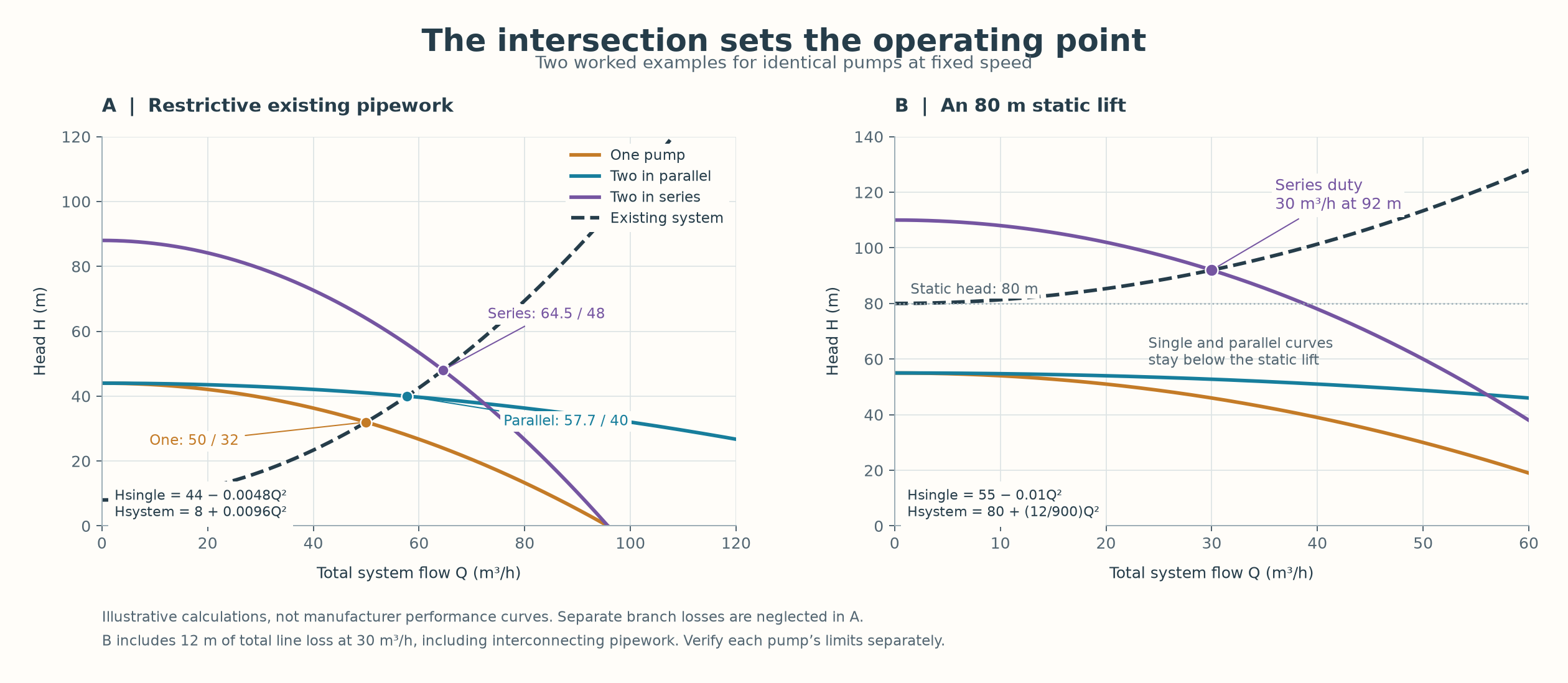
One pump operates at 50 m³/h and 32 m. Static head is 8 m, so friction loss at that flow is 24 m:
K = (32 − 8)/50² = 0.0096
The existing system curve is H_system = 8 + 0.0096Q_total². At 100 m³/h, it requires 104 m, not 32 m.
Using the illustrative single-pump curve above, the parallel pair has H_parallel = 44 − 0.0012Q_total². Its intersection with the existing system is approximately 57.7 m³/h at 40 m. Each pump delivers about 28.9 m³/h.
For this system, the second parallel pump adds about 15% total flow, while moving each pump to a lower individual flow. We still need to check whether that point lies within each pump’s operating limits. The same pumps in series intersect the system curve at about 64.5 m³/h and 48 m—also short of 100 m³/h.
To achieve 100 m³/h at 32 m with the parallel pair, the piping would need an effective K of 0.0024 under these assumptions. That means reducing resistance through an engineered piping change, not simply adding a pump.
| Piping condition | Pumps running | Total flow, m³/h | Head, m | Flow through each running pump, m³/h |
|---|---|---|---|---|
| Existing, K = 0.0096 | Two in parallel | 57.7 | 40 | 28.9 |
| Existing, K = 0.0096 | Một | 50 | 32 | 50 |
| Revised, K = 0.0024 | Two in parallel | 100 | 32 | 50 |
| Revised, K = 0.0024 | Một | 70.7 | 20 | 70.7 |
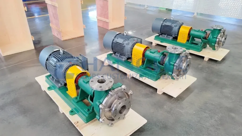
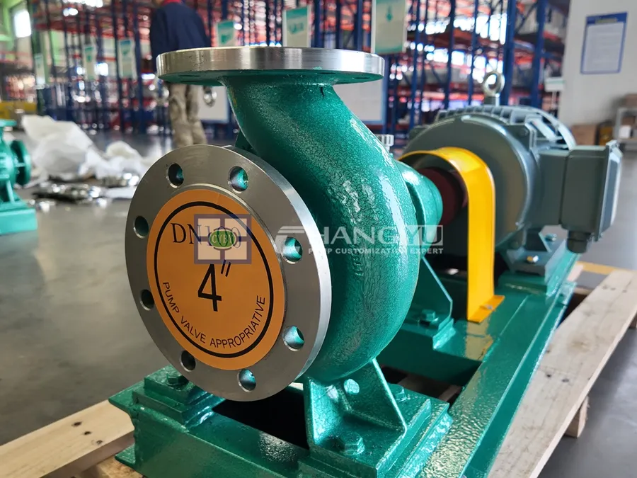
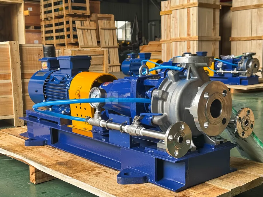
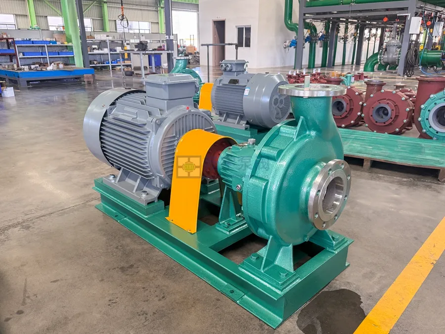
For a particle-free liquid compatible with the selected materials and seals, we would include our CYA horizontal single-stage stainless steel pump in the assessment. The product page is a starting point; the exact model curve, pressure limits, and operating region must support the combination.

Check Whether Both Parallel Pumps Will Contribute
When the pumps share a header, their head characteristics need to be compatible. Identical models make the assessment simpler, but different pumps can work together if their curves and controls support a stable shared duty.
We check each pump against the actual header head, including its branch losses and check-valve opening requirement. Exceeding static head at shutoff is necessary in many transfer systems, but it does not prove that a pump can join an already pressurized header.
If the header pressure exceeds one pump’s available head, a correctly functioning discharge check valve prevents reverse flow. That pump may contribute no flow. Without effective reverse-flow protection, backflow becomes possible. We do not assume a running motor means that pump is delivering liquid.
The common suction pipe must supply the combined flow without unacceptable pressure loss. We include branch size, strainers, minimum tank level, and check valves in the calculation.
High-Head Example: An 80 m Lift
In this second example, water must overcome 80 m static lift plus 12 m total friction loss at 30 m³/h. The required pump head is 92 m.
Suppose each illustrative pump follows H_single = 55 − 0.01Q². At 30 m³/h, each produces 46 m; the series pair produces 92 m. With H_system = 80 + (12/900)Q², the curves intersect at 30 m³/h and 92 m.
At 30 m³/h, both pumps must operate within their allowable flow ranges, with acceptable efficiency, power and NPSH margin. Their rated flows need not be identical.
This comparison also shows why shutoff head matters. Each pump’s shutoff head is 55 m, below the 80 m static lift. Neither can maintain forward delivery alone, even with an ideal bypass around the stopped unit. Parallel operation of these pumps cannot overcome that lift either.
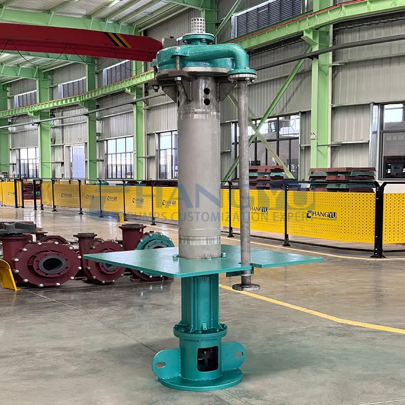
For a high-head application, we compare pumps in parallel vs series with a suitable multistage pump. Two separate pumps add pipework, seals, controls and maintenance tasks that should be justified by the installation.
Series Pressure: Check the Inlet and the Whole Pressure Envelope
Pressure checks can decide pumps in parallel vs series before efficiency does. The second pump receives pressure created by the first, then adds its own differential head.
If the two measurement points have equal elevation and velocity:
p_inlet,2 ≈ p_discharge,1 − Δp_interconnecting pipe
If elevations or pipe diameters differ, include the elevation and velocity-head terms. Use the same pressure basis throughout; use absolute pressure for NPSH calculations.
In the water example, assume the first inlet is at zero gauge pressure, elevation and velocity corrections across the pumps are negligible, and 3 m of the total 12 m loss occurs between pumps:
- First discharge: 46 × 0.00981 ≈ 0.451 MPa gauge.
- Second inlet: (46 − 3) × 0.00981 ≈ 0.422 MPa gauge.
- Second discharge: (46 − 3 + 46) × 0.00981 ≈ 0.873 MPa gauge.
On the series side, checking only the second inlet would miss the higher discharge pressure. We require confirmation of the allowable inlet pressure, casing pressure, seal-chamber conditions, flanges and temperature-dependent limits for each selected unit. A flange marking alone does not establish the assembled pump’s rating.
At zero flow, the illustrative pair could develop about 1.08 MPa gauge with the same source pressure and negligible interconnecting loss. That excludes surge. We check maximum source pressure, shutoff and transient conditions separately from normal duty. Moving the booster uphill changes local inlet pressure, but requires recalculating the whole installation.
Pumps in Parallel vs Series: What Should the Controls Protect?
A control proposal for pumps in parallel vs series should identify the permitted operating combinations, minimum-flow requirements and response to loss of a pump or utility. For pumps in series and parallel, review check valves, isolation and any proposed bypass against the piping drawing and the expected pressure conditions.
For pumps in parallel vs series, ask how starting, stopping and changeover affect flow and pressure. A running indication alone cannot confirm useful delivery. The required measurements, alarms and shutdown logic should follow the assessed operating envelope and the manufacturer’s requirements for the selected pumps.
What Happens When One Pump Stops?
Under single-pump operation, we recalculate the duty rather than assuming “half capacity.”
In the revised parallel system, total flow falls from 100 to 70.7 m³/h. However, the remaining pump’s own flow rises from 50 to 70.7 m³/h. We check absorbed power, motor capacity and NPSH at that new point. Overload is possible; the actual power curve determines it.
For NPSH, we use the lowest credible source level, highest relevant temperature, vapor pressure and suction losses. NPSH available must exceed the pump’s stated requirement by the appropriate application margin. A published NPSH3 value already represents a defined head-drop condition; it is not a guarantee of cavitation-free operation. [4]
In series, the stopped pump can obstruct the flow path. A bypass must be deliberately designed if operation through a single pump is intended. Even with a bypass, the 55 m shutoff head in the high-lift example cannot overcome 80 m static head.
At this point, the question is no longer just capacity; it is continuity of service. Alternating two pumps that are both needed for head does not create redundancy. Continuous service may require a standby booster with suitable switching pipework, a complete standby train, or another configuration capable of meeting the stated failure duty. The required changeover time belongs in the enquiry.
Pump Series vs Parallel: What Must the Quotation Show?
A pump series vs parallel comparison should include both feasible arrangements on the same duty basis. For pumps in parallel vs series, request the combined curve, each pump’s individual operating point, absorbed power and local pressure, with the assumed source level, pipe resistance, speed and liquid properties stated.
Before approving pumps in parallel vs series, agree what the system must deliver during normal operation and after one pump stops. Ask the supplier to identify any piping changes, pressure-rating constraints, controls or standby equipment needed to meet those two duties.
Data for a Useful Two-Pump Quotation
When we assess pumps in parallel vs series at ChangYu Pump, a measured curve or a clear piping sketch helps more than a preferred arrangement alone. Please include:
- Liquid: name, full composition or concentration, temperature range, density, viscosity, pH, and solids concentration and particle size where relevant.
- Duty: minimum, normal and maximum total flow; required total head or destination pressure; and the demand after one pump stops.
- System: source and destination levels and pressures, pipe inside diameters and lengths, fittings, valves, strainers and equipment losses.
- Existing equipment: model, speed, impeller diameter, H–Q/power/NPSH curves, measured flow, suction and discharge pressures, and motor current at known conditions.
- Site requirements: voltage, frequency, variable-speed controls, hazardous-area requirements where applicable, installation space and acceptable interruption time.
Ask the quotation to include the combined curve, each pump’s operating point, pressure checks and the one-pump duty. The U.S. Department of Energy’s pumping-system sourcebook also emphasizes evaluating the system as a whole. [5]
Email: [email protected]
TEL/WA: +86-13651913727
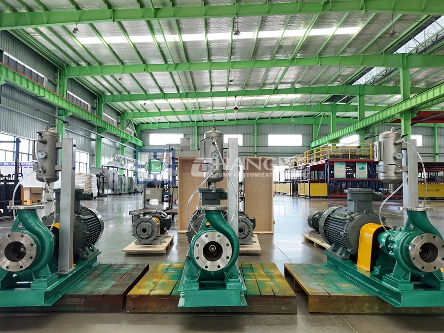
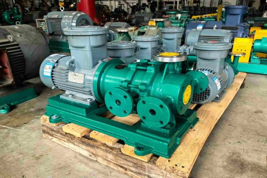
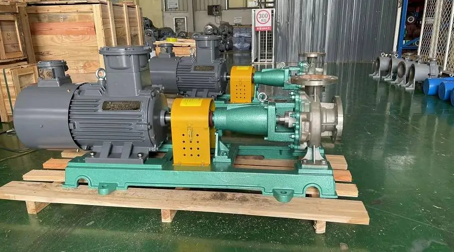
Của chúng tôi dải bơm thép không gỉ provides the model shortlist; liquid compatibility and the calculated duty decide which configurations remain suitable. Stainless steel alone does not establish suitability for every corrosive or particle-bearing liquid.

Câu hỏi thường gặp
Will two pumps in parallel double the flow?
Only under near-constant required head and suitable pump conditions. In a fixed pipeline, higher total flow increases losses. To compare pumps in parallel vs series, read the combined-curve intersection rather than doubling the original flow.
Does series operation double the operating head?
Identical pumps double the curve head at a specified flow, before interconnecting losses. The resulting system duty can move to a different flow. Calculate the new intersection instead of doubling the old gauge reading.
Can we combine different pump models?
Yes, with a curve-based assessment. Parallel pumps need compatible head characteristics; series pumps need a shared acceptable flow range. In either case, verify each unit’s power, suction conditions and pressure limits.
Is a parallel pair automatically safer after a pump failure?
No. It offers useful flexibility only if the remaining pump meets the required failure duty within its limits. In pumps in parallel vs series, redundancy is a verified operating condition, not simply a count of installed pumps.
Can series and parallel arrangements be mixed?
Yes. Parallel series-trains are one possible arrangement. Build the curve for each train, combine the trains at common header conditions, and check the relevant failure combinations and controls.
If you are choosing pumps in parallel vs series, send ChangYu Pump your duty data with the existing model, available curves and a piping sketch. We can use that information to assess the configuration and prepare a quotation around the required duty—including what the system must deliver when one pump stops.

For a pump series vs parallel review, send the actual curves, piping sketch and the duty required when one unit stops. We assess pumps in parallel vs series against that shared basis before discussing the configuration and quotation.
Tài liệu tham khảo
- Hydraulic Institute Data Tool — Pump Curves: combined curves for parallel and series arrangements.
- Hydraulic Institute Data Tool — System Curves và Combined Pump & System Curves: static head, flow-dependent losses and operating-point intersections.
- Hydraulic Institute — Five Keys to Understanding Parallel Pump Optimization: pump matching and limits on added flow.
- Hydraulic Institute — Pump FAQs: interpreting pump curves, NPSH3 and application margins.
- U.S. Department of Energy — Improving Pumping System Performance: A Sourcebook for Industry: system assessment, equipment selection and operating considerations.